Brake system for motor vehicles

A technology for braking equipment, motor vehicles, applied in the direction of brakes, foot start devices, etc.

Inactive Publication Date: 2007-09-19
CONTINENTAL TEVES AG & CO OHG
View PDF1 Cites 42 Cited by
  • Summary
  • Abstract
  • Description
  • Claims
  • Application Information

AI Technical Summary

Problems solved by technology

In the braking system of the prior art, it is considered to be disadvantageous that the fact that it is only possible to assist / support the damage caused by the driver of the vehicle is when the electronics and energy supply (battery) in the vehicle are active. power

Method used


Image

  • Brake system for motor vehicles
  • Brake system for motor vehicles

Examples


Embodiment Construction

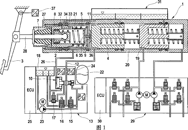
[0018] The brake system according to the invention shown in the figures has a brake pedal 3 which is operatively connected via an actuating rod 28 to a first piston 2 . The brake pedal travel can be detected by a rotation angle sensor 37 . The first piston 2 is arranged in a fourth piston 8, wherein a simulator chamber 21 is formed between the first and fourth piston 8, in which chamber a compression spring 6 is arranged, which makes the The first piston 2 rests on the fourth piston 8 . The fourth piston 8 is movably guided in a third piston 5 and delimits in the third piston a hydraulic chamber 9 which communicates with the simulator chamber 21 via an opening or a channel 35 . The relative movement of the fourth piston 8 relative to the third piston 5 blocks off the channel 35 , for which purpose the piston 5 is provided with a sealing element 36 . Piston seals, through which fluid can flow in a manner related to piston travel, can be used as an alternative to this isolatio...


PUM


Abstract

The invention relates to a brake system with a pedal travel simulator that, during the braking mode brake-by-wire , conveys a comfortable pedal feel to the vehicle driver. In order to boost the actuation force even in the event of a breakdown of the control electronics or loss of electric power supply, the invention provides that a fourth piston (8) is mounted between the first (2) and the third piston (5), and this fourth piston, while interacting with the third piston (5), delimits a hydraulic chamber (9) having a hydraulic connection to a pressure medium reservoir (31), said connection being able to be blocked by an actuation of the brake pedal, and pressure can be built up in the chamber by the actuation forces. The invention also provides that a valve assembly (10) can be controlled by the hydraulic pressure built-up inside the chamber (9), and the pressure built-up in the intermediate space (11) can be changed by this valve assembly.

Description

technical field [0001] The invention relates to a braking device for a motor vehicle, comprising: a master cylinder connectable to a wheel brake cylinder; a first piston engaged with a brake pedal via a push rod transmitting an actuation force; an actuating master cylinder a second piston of the cylinder; a third piston actuatable by the first piston and capable of forming a force-transmitting connection with the second piston; at least one elastic element forming a pedal stroke simulator which is operated during "brake-by-wire" In the operating mode of the vehicle, a pleasant pedal feeling is given to the driver of the vehicle; said device has means for coupling the movements of the first and third pistons according to the travel distance of the third piston in a housing start; the device has a gap between the second and third pistons available for hydraulic pressure, wherein pressurization in the gap loads the second and third pistons in opposite directions; and the device h...

Claims


Application Information

Patent Timeline
Patent Type & Authority Applications(China)
IPC IPC(8): B60T8/40B60T7/04
Inventor S·德鲁姆L·席尔
Owner CONTINENTAL TEVES AG & CO OHG
Why Eureka
Try Eureka