
Engines connecting rod bushing

A technology for engine connecting rods and bushings, applied in the field of bushings, can solve problems such as difficulty in forming a stable oil film and low oil intake into the oil storage tank, and achieve the effects of stable oil film, enhanced reliability, and extended service life

Inactive Publication Date: 2007-09-26
WEICHAI POWER CO LTD
View PDF0 Cites 11 Cited by
  • Summary
  • Abstract
  • Description
  • Claims
  • Application Information

AI Technical Summary

Problems solved by technology

[0004] The technical problem to be solved by the present invention is to provide an engine connecting rod bushing to solve the problem that when the engine is working, the amount of oil entering the oil storage tank is small and it is difficult to form a stable oil film

Method used


Image

  • Engines connecting rod bushing
  • Engines connecting rod bushing
  • Engines connecting rod bushing

Examples


Embodiment Construction

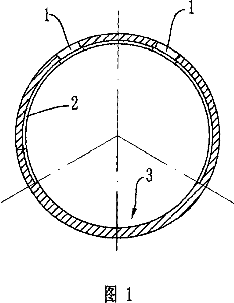
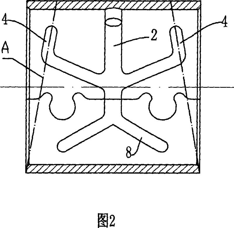
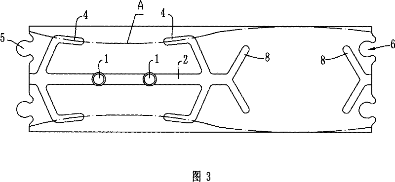
[0015] As shown in Figures 1 and 3 together, the engine connecting rod bushing has a cylindrical body, which includes a lower pressure bearing area 3 for bearing the pressure of the piston pin when the piston moves from the top dead center to the bottom dead center. The circumference angle of the lower pressure-bearing area 3 is about 110°~130°, and the upper pressure-bearing area is used to bear the pressure of the piston pin when the piston moves from the bottom dead center to the top dead center. The upper pressure-bearing area is provided with an oil hole 1, and there are two oil holes 1, and the two oil holes 1 are symmetrically arranged on both sides of the vertical plane of the upper pressure-bearing area. The inner wall of the body is provided with a main oil storage tank 2 extending in the circumferential direction. The main oil storage tank 2 is located in the axial middle of the body and communicates with the oil hole 1. The main oil storage tank 2 ends at the In th...


PUM


Abstract

The engine linking bar sleeve with cylindrical body that comprises the lower bearing area for the pressure from the top dead end to the lower dead end of the piston pin, and the up bearing area bearing the pressure from lower end point to the top end point, with the said up end bearing area with oil holes, the said body inner wall having main oil storage slot sticking to the surrounding area, the said main oil storage slot connecting with the said oil hole, the said body inner wall having sub oil storage slot whose one end connecting with the main oil storage slot, the other end open at the said end surface. It has strong bearing ability, improved lubrication effect, improved reliability of the piston linking bar and extended durability.

Description

technical field [0001] The invention relates to the technical field of bushings, in particular to a bushing installed on a small end of an engine connecting rod. Background technique [0002] The engine connecting rod bushing is installed on the small end of the engine connecting rod, and acts as a sliding bearing between the piston pin and the engine connecting rod. When the piston moves from the top dead center to the bottom dead center, the piston pin exerts pressure on the lower part of the bushing; and when the piston moves from the bottom dead center to the top dead center, the piston pin exerts pressure on the upper part of the bushing. Due to the limitation of the swing angle of the connecting rod, the lower area bearing the pressure of the piston pin (hereinafter referred to as the lower pressure area) and the upper area bearing the pressure of the piston pin (hereinafter referred to as the upper pressure area) are both definite areas. [0003] In order to ensure t...

Claims


Application Information

Patent Timeline
Patent Type & Authority Applications(China)
IPC IPC(8): F16C9/04
Inventor 王进峰李昌信
Owner WEICHAI POWER CO LTD
Learn More