
Actuator

A technology for actuators and motors, applied in power transmission/actuator features, electric components, transmissions, etc., can solve the problems of complex joint surfaces, increased number of parts, and difficulty in obtaining sealing, etc., to achieve small size The effects of simplification, easy assembly, and improved airtightness

Inactive Publication Date: 2007-09-26
HONDA LOCK MFG CO LTD
View PDF1 Cites 14 Cited by
  • Summary
  • Abstract
  • Description
  • Claims
  • Application Information

AI Technical Summary

Problems solved by technology

Therefore, when assembling the screw shaft, it is necessary to shorten the coil spring against the elastic force of the coil spring, which makes the assembly work difficult.
Moreover, since the through-hole through which the output shaft is inserted is formed between a pair of half-shells combined with each other, the joint surface of the two half-shells is complicated, and it is difficult to obtain good sealing performance.
[0006] On the other hand, in the actuator disclosed in Patent Document 2, a through hole through which the output shaft is inserted is provided in one of the two half-cases to simplify the joining surface of the two half-cases to obtain Sufficient sealing performance, but since a rack and pinion are used as part of the power conversion unit that converts the rotational power of the motor into the axial power of the output shaft, the length of the rack has to be set relatively long. In addition, Since the reduction ratio of the reduction mechanism between the pinion and the motor needs to be set relatively large, the installation space of the reduction mechanism becomes relatively large, resulting in an increase in the overall size of the case.
Also, in order to limit the axial reciprocating end of the output shaft, a pair of stoppers are required, resulting in an increase in the number of parts

Method used


Image

  • Actuator
  • Actuator
  • Actuator

Examples


Embodiment Construction

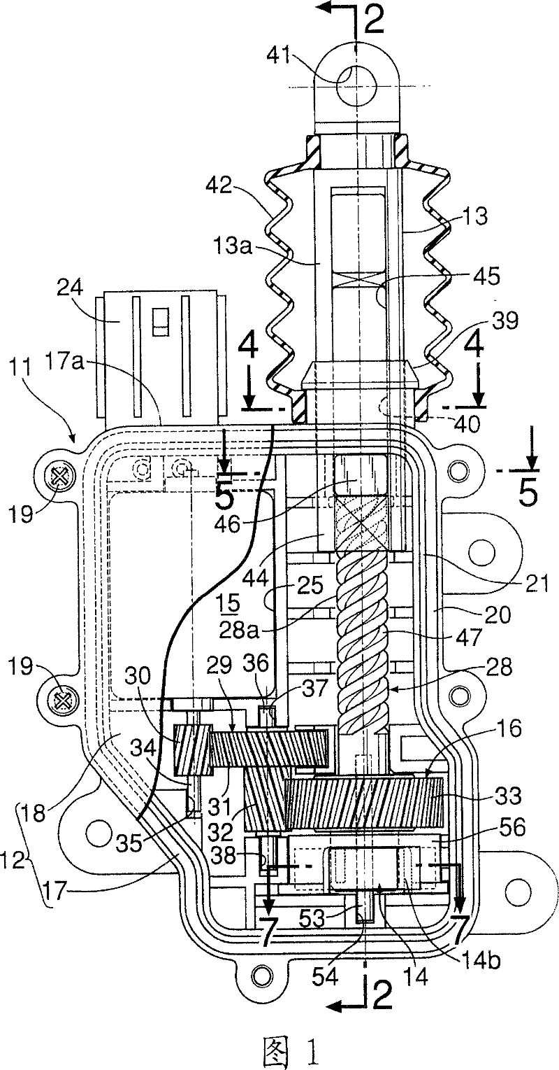
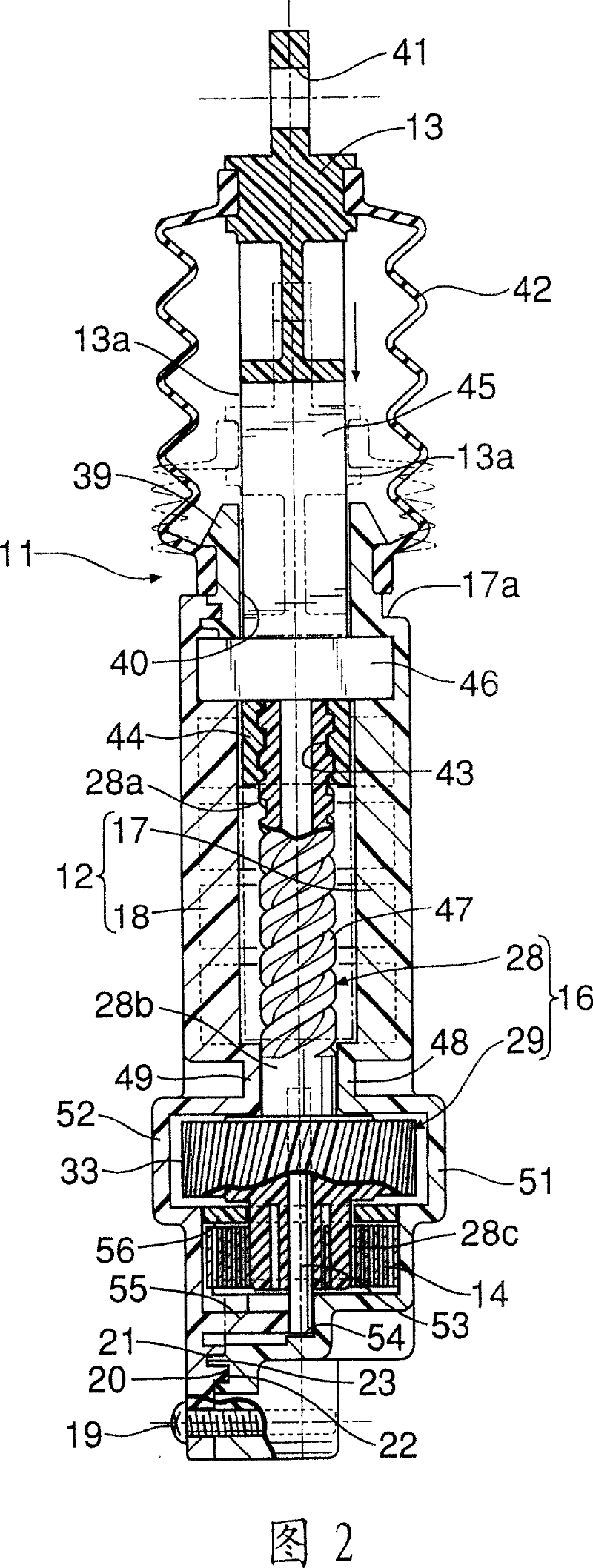
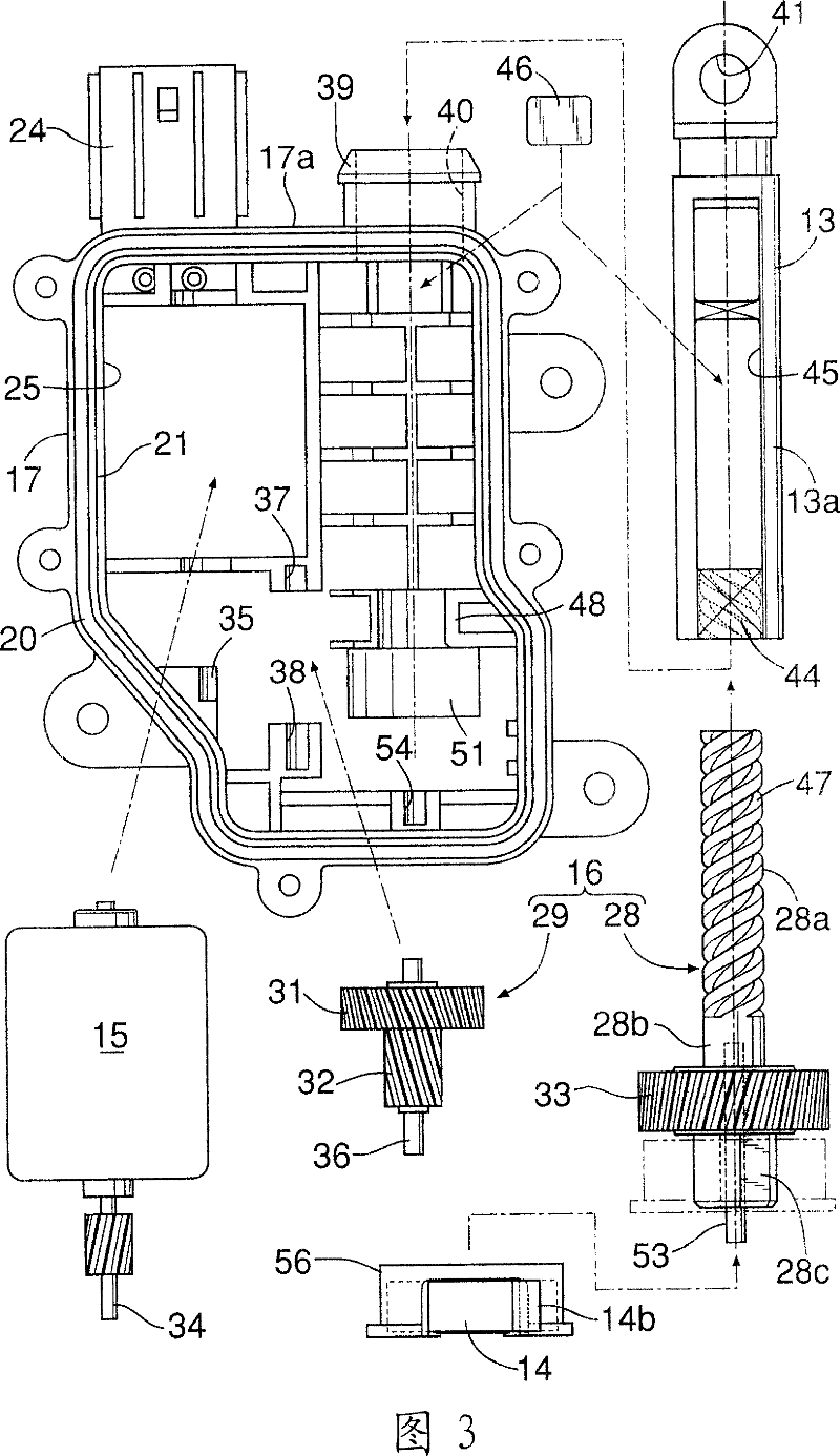
[0025] Fig. 1~Fig. 8 shows an embodiment of the present invention, and Fig. 1 is the partially sectioned front view of actuator, and Fig. 2 is the sectional view along line 2-2 in Fig. 1, and Fig. 3 is the exploded representation first half Figure 4 is a cross-sectional view along line 4-4 in Figure 1, Figure 5 is a cross-sectional view along line 5-5 in Figure 1, Figure 6 It is a perspective view of an output shaft and a stopper, FIG. 7 is a sectional view along line 7-7 in FIG. 1 , and FIG. 8 is an exploded perspective view of a scroll spring and a spring housing.

[0026] First in Fig. 1, the actuator 11, for example, exerts a driving force for releasing the locked state of the door lock device of the automobile, and the actuator 11 includes: a housing 12; an output shaft 13, which can reciprocate in the axial direction ground supported on the casing 12; the scroll spring 14, which applies force to the side that increases the protruding amount of the output shaft 13 from th...


PUM


Abstract

The invention provides an actuator, in which an output shaft applied with elasticity in protruding direction is supported axially in reciprocating action mode on a casing with a motor and a power conversion unit between the motor and the output shaft stored therein. The actuator has adequate sealing, easy assembly of lead screw shaft, casing miniaturization and reduction of component number. The lead screw shaft is a part of the power conversion unit, and the side wall of a first half-casing is provided with a through hole penetrated by the output shaft which is provided with a screwing part screwed with the lead screw shaft at the axial inner end side and a long hole extending axially. A stopper limiting the axial moving end of the output shaft penetrates into the long hole between the inner surface of the side wall and the screwing part, fitted with and supported on the first half-casing, and a volute spring is arranged between the other end of the lead screw shaft and the first half-casing.

Description

technical field [0001] The present invention relates to an actuator that exerts, for example, a driving force for unlocking a locked state of a door lock device of an automobile, and an opening and closing power of a cover body of a fuel cap, and particularly relates to an actuator in which a housing is formed by A first half case and a second half case combined with each other are formed, and an output shaft to which elastic force is applied to a side protruding from the case is supported on the case so as to reciprocate in the axial direction, and the power conversion unit is provided. Between the electric motor and the above-mentioned output shaft, and for converting the rotational power of the electric motor into the axial power for driving the above-mentioned output shaft to the side that pulls the above-mentioned output shaft into the above-mentioned housing, the above-mentioned electric motor and the above-mentioned power conversion unit are housed in in the above housi...

Claims


Application Information

Patent Timeline
IPC IPC(8): F16H19/02F16H25/20E05B65/20E05B81/28E05B81/34E05B83/36F16H1/06F16H33/02H02K7/06
Inventor 日高圭亮
Owner HONDA LOCK MFG CO LTD
Learn More