High-pressure resistant hose and manufacturing method thereof

A high-pressure, hose-resistant technology, applied in the direction of hoses, hose connection devices, pipes, etc., can solve problems such as troublesome post-processing, and achieve the effect of improving sealing performance

Inactive Publication Date: 2007-09-26
SUMITOMO RIKO CO LTD
View PDF1 Cites 5 Cited by
  • Summary
  • Abstract
  • Description
  • Claims
  • Application Information

AI Technical Summary

Problems solved by technology

[0014] However, when forming the receiving portion that compresses the hose base, during the mating contact of the retaining die segments, the material of the outer surface layer may be extruded from between the retaining die segments and formed in the finished hose body. flash
This makes post-processing after the hose body is made very cumbersome

Method used


Image

  • High-pressure resistant hose and manufacturing method thereof
  • High-pressure resistant hose and manufacturing method thereof
  • High-pressure resistant hose and manufacturing method thereof

Examples


Embodiment Construction

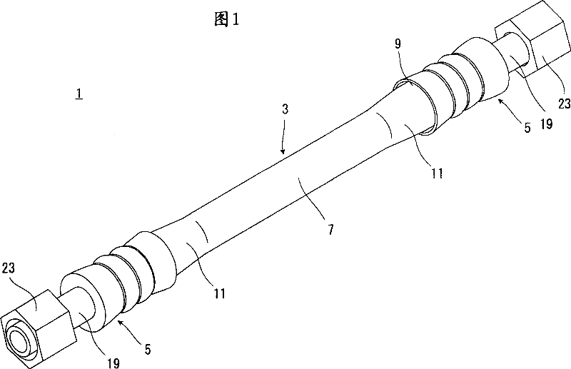
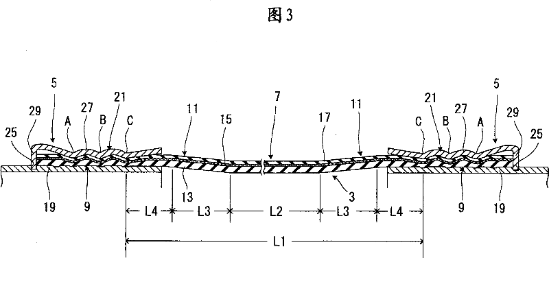
[0042]The high-pressure hose 1 in FIG. 1 is used, for example, as an air-conditioning hose of a motor vehicle. The anti-high pressure hose 1 comprises a hose body 3 to which metal joint fittings (couplings or joints) 5 are securely fitted to two axially opposite ends of the hose body. The hose main body 3 has a main portion 7 located at its axially central portion, swaged portions or portions to be swaged (tightened portions) 9, 9 located at its axially opposite ends, and portions located at the main portions 7 and swaged The tapered portion 11, 11 between the forged portion 9. The main portion 7 is formed in an elongated tubular shape and has the same inner and outer diameters throughout its length. Each swaged portion 9 has a tubular shape with an inner diameter and an outer diameter larger than those of the main portion 7 . Each tapered portion 11 is tapered with a diameter decreasing from said swaged portion 9 to said main portion 7 .

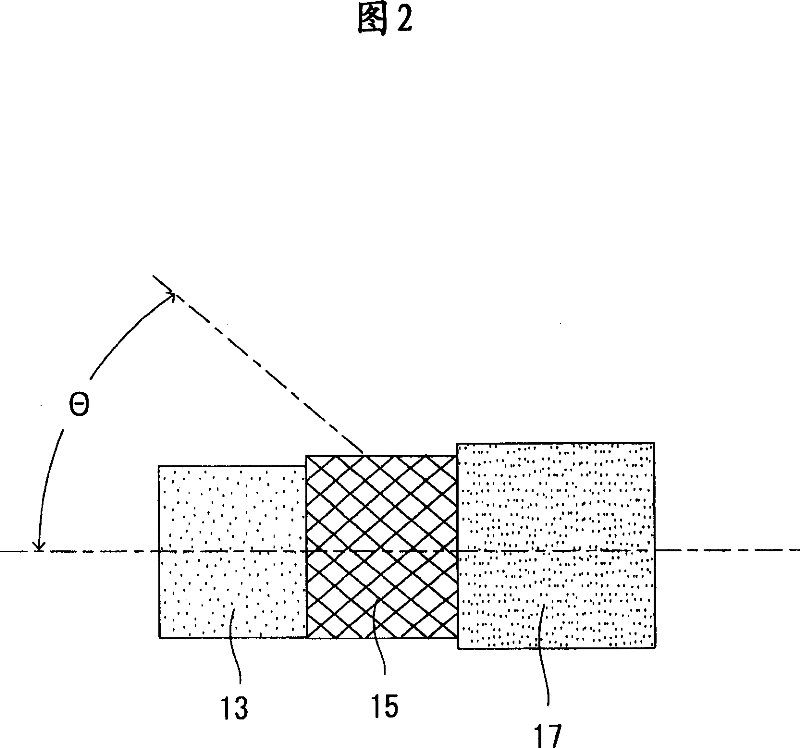
[0043] As shown in FIG. 2 , the h...


PUM


Abstract

The present invention provides a high pressure resistant hose of low longitudinal deformation quantity under a pressurized condition, capable of being stably laid in a narrow pipe layout space, and of good vibration absorbing properties. A hose body having an inner surface side layer 13, a reinforcement layer 15 and an outer surface side layer 17 laminated and including constant inner diameter, outer diameter and wall thickness over whole length is formed. End part sides in a longitudinal direction of the hose body are expanded to form a main part 7 of a small diameter, a caulking part 9 of a large diameter and a taper part 1. Braiding angle of the main part 7 is set to 48 degree or more and less the 54 degree. Braiding angles of the caulking part 9 and the taper part 11 are set to 68 degree or less with exceeding 57 degree, roughly 61 degree or less with exceeding 55 degree from original range 48 degree or more and less than 54 degree by expansion.

Description

technical field [0001] The present invention relates to a high-pressure resistant hose such as an automobile air-conditioning hose and a method for manufacturing the high-pressure resistant hose. Background technique [0002] A hose used for an automobile air conditioner hose has a structure in which a reinforcing layer made of a reinforcing wire member or a reinforcing yarn (for example, a reinforcing wire member is helically wound) is formed on the outside of an inner surface rubber layer, the The outer side of the reinforcement layer is covered with an outer surface rubber layer (for example, refer to Patent Document 1). In order to reduce the permeation of the internal fluid, ie refrigerant, to prevent global warming, such hoses are usually provided with a resin barrier layer on the inside of the inner surface layer. [0003] Since this type of air conditioner hose is used to connect the engine side and the vehicle body side, it is preferable that this type of air condi...

Claims


Application Information

Patent Timeline
Patent Type & Authority Applications(China)
IPC IPC(8): F16L11/08F16L33/22
Inventor 大海荣一
Owner SUMITOMO RIKO CO LTD
Why Eureka
Try Eureka