
Casing

A shell and shell wall technology, which is applied in the directions of engine sealing, cable joints, electrical components, etc., can solve the problem of time-consuming, and achieve the effects of easy processing, weight reduction, and simple processing.

Inactive Publication Date: 2007-09-26
WEIDMULLER INTERFACE GMBH & CO KG
View PDF0 Cites 3 Cited by
  • Summary
  • Abstract
  • Description
  • Claims
  • Application Information

AI Technical Summary

Problems solved by technology

This procedure should therefore be carried out with extreme care and correspondingly very time-consuming

Method used


Image

  • Casing
  • Casing
  • Casing

Examples


Embodiment Construction

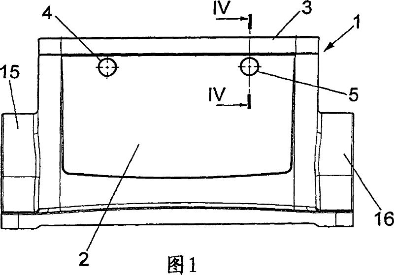
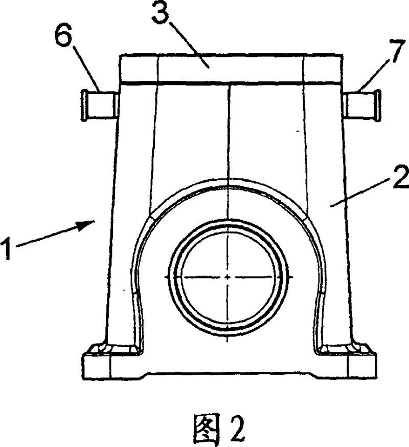
[0026] The enclosures shown in Figures 1 and 2 can be considered as examples. It essentially comprises a housing lower part 2 that is box-shaped and closed with a removable cover 3 . In the upper region of the two broad sides, the housing wall is provided with two through-openings 4 , 5 in each case. The two pins 6 , 7 are fixedly inserted into these through-holes in a manner that will be explained in more detail. When the housing is a plug connector housing of a heavy-duty electrical plug connector, these pins 6 , 7 can be, for example, retaining pins or stop pins for locking clamping clips.

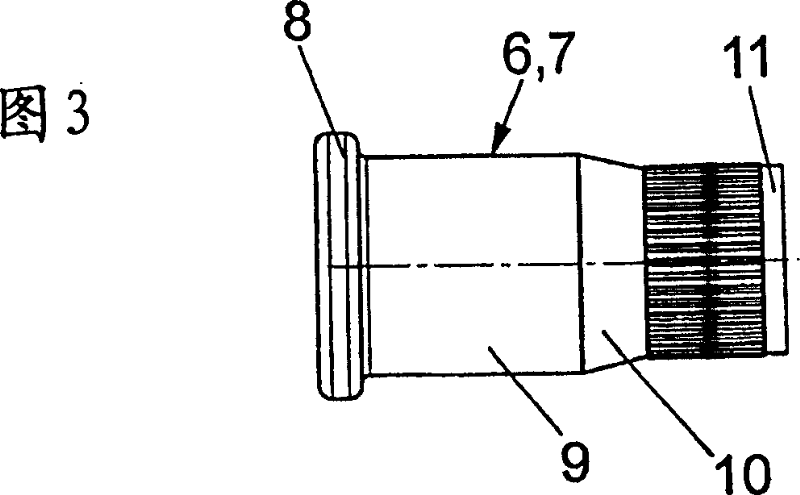
[0027] As shown in FIG. 3, in this embodiment, each pin 6, 7 consists of four sections. The free ends of the pins 6 , 7 inserted into the housing wall are a flange 8 , behind which a cylindrical part 9 , a sealing cone 10 and an insertion region 11 opposite the flange 8 adjoin. The insertion area 11 of the pins 6 , 7 is smaller in diameter than the cylindrical section 9 . As shown i...


PUM


Abstract

The invention provides a housing (1), especially a plug connector housing which is made of metal, wherein at least a housing wall is provided with a via hole (4, 5), an inserting region (11) of an end side of a pin (6, 7) is arranged in the via hole in a manner that cann't be rotated, wherein cooperation between each of the via holes (4, 5) of the housing wall and the inserting region (11) of the pin (6, 7) is pressing-cooperation.

Description

technical field [0001] The invention relates to a housing, in particular a plug-in connector housing, which is made of a metal and in which at least one housing wall is provided with at least one through-opening into which an end-side insertion region of a pin is inserted non-rotatably. In the through hole, wherein the fit between the through hole and the insertion area of ​​the pin is designed to be at least watertight, but preferably airtight. Background technique [0002] In said housing, for example a plug-in connector housing, two pins are inserted in openings in opposite housing walls, which protrude relative to the outer surface. In addition, the housing is provided with some connections for electrical leads. The pin is designed as a fixing pin or a stop pin. [0003] In order to prevent fluid from flowing through, the fit between each through-opening and the insertion region of the pin inserted therein should be substantially airtight. The through-hole and the ins...

Claims


Application Information

Patent Timeline
Patent Type & Authority Applications(China)
IPC IPC(8): H02G15/10H02G3/06F16J15/04
CPCH01R13/73
Inventor M·德雷维斯P·施佩尔
Owner WEIDMULLER INTERFACE GMBH & CO KG
Learn More