Supercharge Your Innovation With Domain-Expert AI Agents!

Antenna and electronic equipment using the same

An antenna, straight line technology, used in the direction of antennas, antenna supports/mounting devices, electrical components, etc.

Inactive Publication Date: 2007-10-03
PANASONIC CORP
View PDF1 Cites 1 Cited by
  • Summary
  • Abstract
  • Description
  • Claims
  • Application Information

AI Technical Summary

Problems solved by technology

[0004] Antenna enlargement is a problem in existing electronic equipment

Method used


Image

  • Antenna and electronic equipment using the same
  • Antenna and electronic equipment using the same
  • Antenna and electronic equipment using the same

Examples


Embodiment Construction

[0066] Hereinafter, one embodiment of the present invention will be described with reference to the drawings.

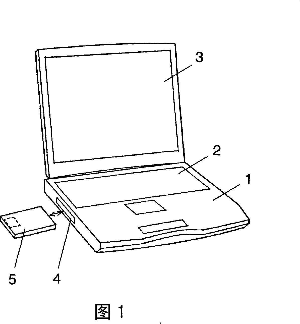
[0067] In FIGS. 1 and 2 , a notebook personal computer 1 includes an input unit 2 and a display unit 3 . In addition, a slot 4 is provided on the side of the input part 2, and a communication module 5 is inserted into the slot 4. As shown in FIG.

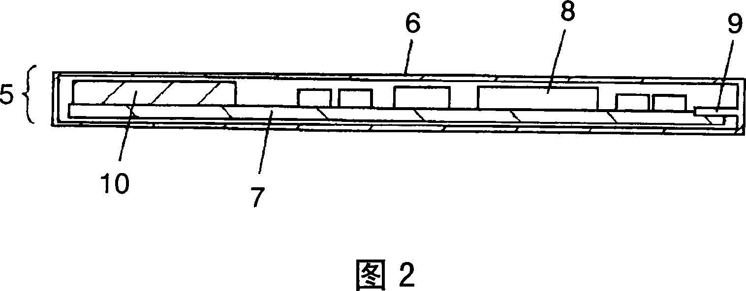
[0068] In the communication module 5 , as shown in FIG. 2 , a circuit board 7 is provided in a plate-shaped case 6 , and various electronic components 8 are mounted on the circuit board 7 . In addition, in a front view of FIG. 2 , a connector 9 for insertion into the slot 4 and electrically coupled is provided on the right side of the circuit board 7 . Similarly, in the front view 2 , the antenna 10 is mounted on the left side of the circuit substrate 7 .

[0069] That is, when the case 6 in FIG. 2 is inserted into the slot 4 in FIG. 1 , the antenna 10 protrudes from the slot 4 to the outside, and thus it is possible to ...


PUM


Abstract

The objective of the present invention is to realize, in an antenna and an electronic equipment using the same, miniaturization of that antenna. To achieve said objective, an antenna electrode (19) is provided on the surface of the main body (18), a grounding electrode (20) is provided on the back face, and a signal electrode (21) is provided on the circumferential face, the antenna electrode (19) being different in length at the X axis from the Y axis. This enables to construct a broad-band antenna with a single piece of antenna, contributing to miniaturization of the antenna.

Description

[0001] The present invention is a divisional application of the application number 200310102534.7 filed on October 22, 2003 by the applicant Matsushita Electric Industrial Co., Ltd., and the title of the invention is "antenna and electronic equipment using it". technical field [0002] The present invention relates to antennas and electronic equipment using the same. Background technique [0003] In existing electronic equipment, such as a personal computer, it is often possible to insert a communication module into a slotted part thereof, and use the personal computer to perform various communication services. In order to perform such communication, a communication module has an antenna provided therein, for example, as described in Japanese Patent Application Laid-Open No. 9-98015. [0004] An antenna enlargement has become a problem in conventional electronic equipment. That is, in recent years, the frequency band used in the communication system has been widened, and in...

Claims


Application Information

Patent Timeline
IPC IPC(8): H01Q13/08H01Q1/24
Inventor 福岛奖难波英树黑田庆
Owner PANASONIC CORP
Features
  • R&D
  • Intellectual Property
  • Life Sciences
  • Materials
  • Tech Scout
  • Unparalleled Data Quality
  • Higher Quality Content
  • 60% Fewer Hallucinations
Learn More