Multipurpose soft tube

A multi-purpose, hose technology, applied in the direction of hoses, suction hoses, pipes, etc., can solve the problems of inability to disassemble, complicated process, high manufacturing cost, etc., and achieve scientific setting, expanded use range, and wide use range Effect

Active Publication Date: 2010-12-15
JINHUA CHUNGUANG TECHNOLOGY CO LTD
View PDF5 Cites 1 Cited by
  • Summary
  • Abstract
  • Description
  • Claims
  • Application Information

AI Technical Summary

Problems solved by technology

[0004] The above-mentioned small tube is directly fixed and bonded on the inner wall of the hose, so that the flexibility, balance, and flexibility of the entire hose assembly are reduced; and because the small tube is sometimes filled with fluid, when the above-mentioned After the small tube is fixed, it cannot be disassembled, so once a hose assembly is made, the type of fluid that can be guided in the small tube is also roughly fixed, and finally the scope of use of the entire hose assembly is limited.
Moreover, when the small tube is connected with a high-temperature fluid, since the small tube is in contact with the hose, heat transfer will occur between the two, thereby making the hose soft, and ultimately affecting the use of the entire multifunctional tube. When bonding to the inner wall of the hose, the process is complicated and the manufacturing cost is relatively high

Method used


Image

  • Multipurpose soft tube
  • Multipurpose soft tube
  • Multipurpose soft tube

Examples


Embodiment 1

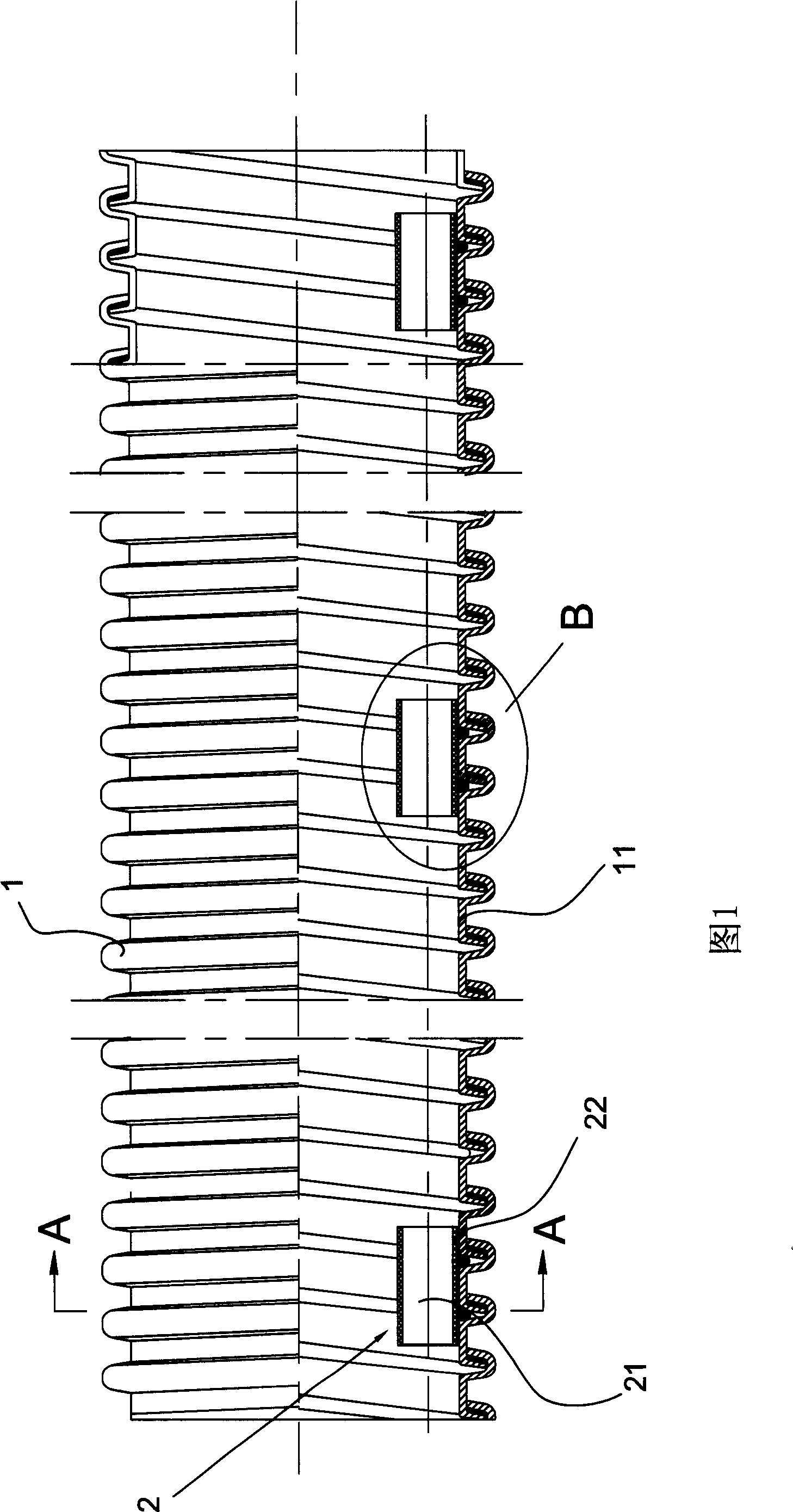
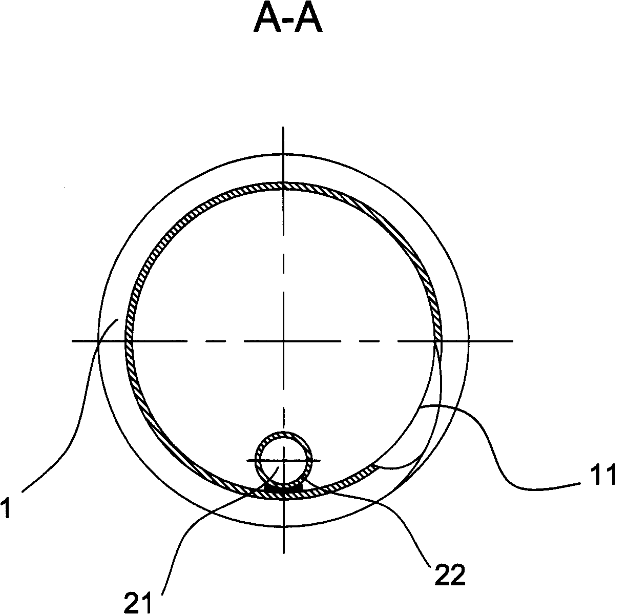
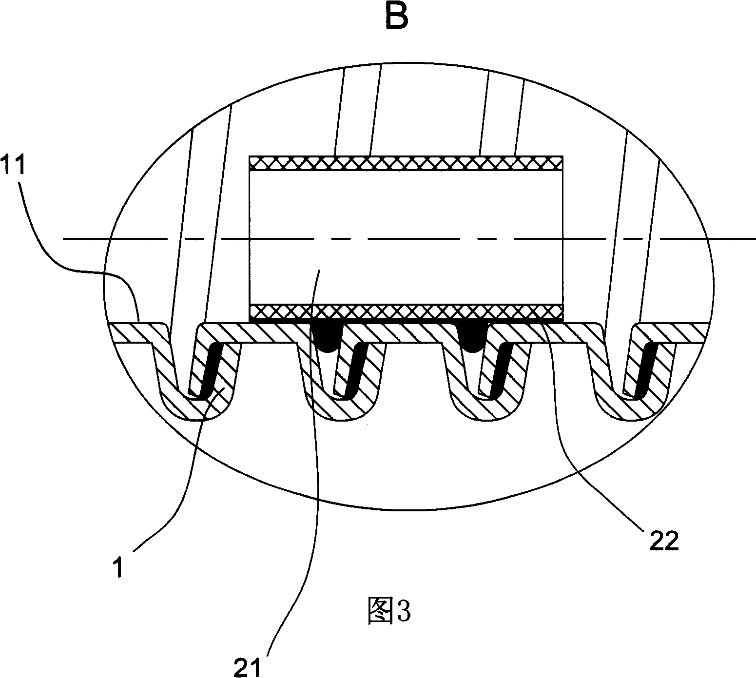
[0053] like Figure 1~6 A multi-purpose hose is shown, which includes a hose 1, and a plurality of positioning pieces 2 arranged at intervals along the length direction of the hose are fixedly arranged on the inner wall surface 11 of the hose. An accommodating channel 21 extending in the length direction.

[0054] In the embodiment shown in the figure, a group of multiple positioning members 2 distributed along the same straight line are fixedly arranged on the inner wall surface 11 of the hose, and the straight line is parallel to the axis of the hose 1 .

[0055] For a non-standard cylindrical hose, if the hose is truncated conical, a plurality of positioning pieces 2 are arranged along the inner wall surface 11 of the hose, and the straight line where the multiple positioning pieces 2 are located is in line with the hose 1. Axis lines intersect.

[0056] Each locator is a single-hole collar 22, such as Figure 1~3 As shown in , a receiving channel 21 extending along the ...

Embodiment 2

[0059] like Figure 4~6 As shown, this multi-purpose hose is roughly the same as the multi-purpose hose in Embodiment 1, except that each positioning part in this embodiment is a porous collar 23, and multiple holes along the length direction of the hose 1 are formed in the porous collar 23. The extended receiving channel 21, shown as a two-hole collar, forms two receiving channels inside it.

Embodiment 3

[0061] like Figure 7-9 The shown multi-purpose hose includes a hose 1, and a plurality of positioning parts 2 arranged at intervals along the length direction of the hose 1 are fixedly arranged on the inner wall surface 11 of the hose. The accommodating channels 21 extending in the length direction of the hose 1 are provided with small tubes 3 inserted in the accommodating channels 21 of the plurality of positioning members 2 , and the small tubes 3 extend along the length direction of the hose 1 .

[0062] Since the small tube 3 is inserted in the positioning part 2, a gap 5 is formed between the small tube outer wall surface 31 and the hose inner wall surface 11 between two adjacent positioning parts 2, and the small tube outer wall surface 31 is formed by the gap 5. It is not in contact with the inner wall surface 11 of the hose. In this way, when working, there will be no direct heat transfer between the small tube 3 and the hose 1, so that the two will not affect each o...


PUM


Abstract

A multipurpose flexible tube is prepared for fixing and setting multiple positioning element being arranged along length direction of soft tube in interval mode on internal wall of said soft tube, setting a containing channel being extended along length direction of soft tube on each said positioning element and enabling to hold small tube or cable by said containing channel.

Description

technical field [0001] The present invention relates to a multipurpose hose which can be used on vacuum cleaners or other industrial equipment. Background technique [0002] At present, the multi-purpose hoses used for electricity, water, and ventilation are provided with a small tube with a smaller diameter on the inner wall of the hose to pass through the cable body or other fluids different from the hose. Usually, this small tube It is fixedly bonded to the inner wall of the hose. For example, the European patent "hose assembly" with the patent number EP-A-574371 discloses a combination of a hose and a plurality of small tubes, wherein the diameter of the small tube is smaller than the diameter of the flexible tube, and the multiple small tubes run through the soft tube. The tubes are respectively fixed on the inner wall of the hose. [0003] The PCT patent document of WO9821024 discloses the processing and operation of the above-mentioned hose assembly. After the whole...

Claims


Application Information

Patent Timeline
Patent Type & Authority Patents(China)
IPC IPC(8): F16L11/127F16L11/118A47L9/24
Inventor 陈正明
Owner JINHUA CHUNGUANG TECHNOLOGY CO LTD
Why Eureka
Try Eureka