
Part assembling hole design system and method

A technology of parts assembly and design system, applied in computing, special data processing applications, instruments, etc., can solve problems such as low design efficiency and achieve the effect of improving design efficiency

Inactive Publication Date: 2010-08-25
HONG FU JIN PRECISION IND (SHENZHEN) CO LTD +1
View PDF0 Cites 0 Cited by
  • Summary
  • Abstract
  • Description
  • Claims
  • Application Information

AI Technical Summary

Problems solved by technology

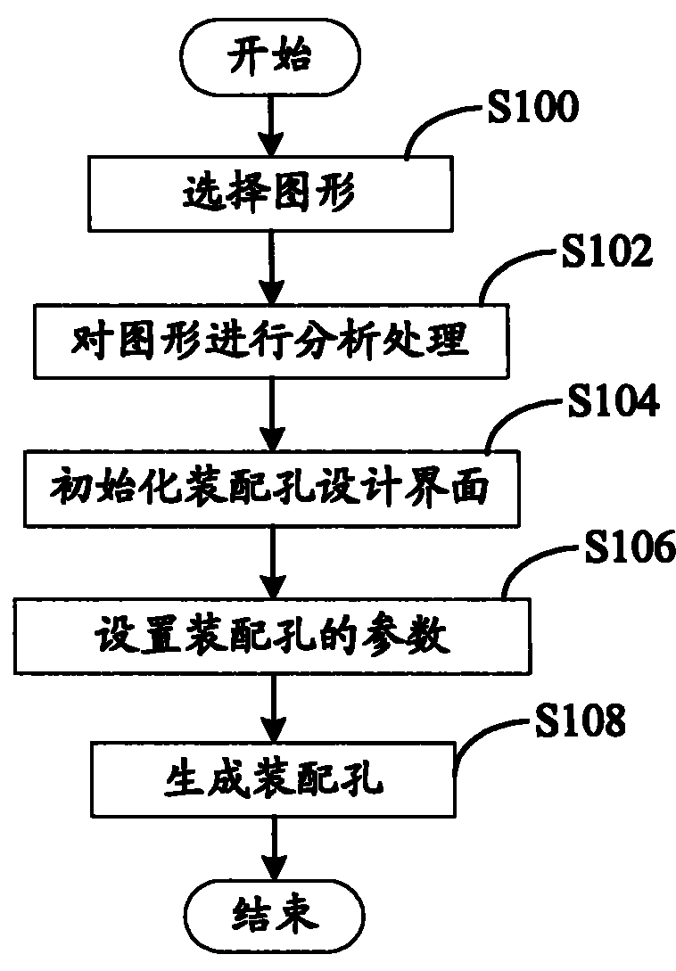
In order to obtain a suitable shape of the working part, the existing method is to manually copy a copy of the main view of the part, and edit it by cutting, concatenating, etc. to obtain the correct shape of the main view of the part, and then manually copy it to the matched part. On the corresponding template, after the parts are disassembled, the hole type, clearance, direction and other information corresponding to the assembly holes on the template must be manually added one by one, so the design efficiency is very low

Method used


Image

  • Part assembling hole design system and method
  • Part assembling hole design system and method
  • Part assembling hole design system and method

Examples


Embodiment Construction

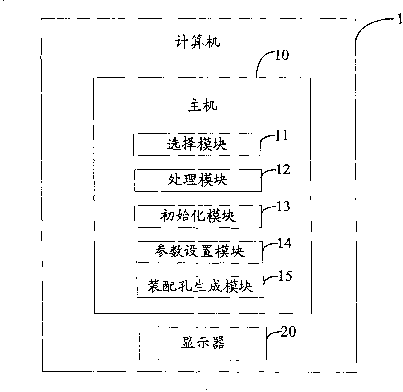
[0015] Referring to FIG. 1 , it is a hardware architecture diagram of a preferred embodiment of the component assembly hole design system of the present invention. The component assembly hole design system includes a computer 1 , and the computer 1 includes a host 10 and a display 20 . Wherein, the host 10 includes a selection module 11 , a processing module 12 , an initialization module 13 , a parameter setting module 14 and an assembly hole generation module 15 .

[0016] Wherein, the selection module 11 is used to select any graphics such as primitives and parts from the design diagram, but when the layer where the graphics is located is locked in the design diagram, the graphics are not selectable. In this preferred embodiment, the design drawing is introduced by taking the mold design drawing as an example. The selection module 11 has two modes for selecting graphics: one is to select the object mode "Object"; mode, it needs to receive the switching command "P" input by...


PUM


Abstract

A method for designing assembly hole on parts includes selecting any pattern from design drawing, carrying out analysis and treatment on selected pattern to conform pattern of required parts, initializing said pattern of parts, making parameter-setting on assembly hole corresponding to said pattern of parts and generating parts assembly hole with relevant attribute in corresponding to assembly hole set-parameter. The system used for realizing said method is also disclosed.

Description

【Technical field】 [0001] The invention relates to a system and method for designing assembly holes of parts. 【Background technique】 [0002] The stamping die is the main process equipment of the stamping process, and the stamping part is completed by the relative movement of the upper and lower dies. The working part of the mold is the part that directly shapes the blank. Therefore, it is a key part on the mold. It is not only precise but also complex. It should meet the following requirements: (1) It should have sufficient strength and cannot be broken or damaged during the stamping process. (2) There should be appropriate requirements for its material and heat treatment to prevent the hardness from being too high and brittle. [0003] If the mold designer wants to add a working part to the designed mold, in addition to drawing and determining the appropriate part shape, he also needs to generate the same assembly hole as the determined working part shape on the correspond...

Claims


Application Information

Patent Timeline
Patent Type & Authority Patents(China)
IPC IPC(8): G06F17/50
Inventor 周晔
Owner HONG FU JIN PRECISION IND (SHENZHEN) CO LTD
Learn More