Fluorescent x-ray analysis apparatus

An analysis device, X-ray technology, applied in measurement devices, analysis materials, material analysis using wave/particle radiation, etc., can solve problems such as increasing X-ray intensity, limited distance, etc.

Active Publication Date: 2012-04-18
HITACHI HIGH TECH SCI CORP
View PDF1 Cites 0 Cited by
  • Summary
  • Abstract
  • Description
  • Claims
  • Application Information

AI Technical Summary

Problems solved by technology

In order to increase the intensity of X-rays incident on the above-mentioned X-ray detector, the above-mentioned X-ray source and the above-mentioned X-ray detector are arranged close to the measurement sample, but since they are arranged towards the same point, if they are close, the two structures will Interference, so the close distance is limited

Method used


Image

  • Fluorescent x-ray analysis apparatus
  • Fluorescent x-ray analysis apparatus
  • Fluorescent x-ray analysis apparatus

Examples


Embodiment Construction

[0065] Embodiments of the present invention will be described with reference to the drawings.

[0066] Figure 8 It is a block diagram of the fluorescent X-ray analysis apparatus of this invention. The X-ray source 1 is controlled by the control unit and the computer unit 82 to irradiate the sample container 8 with primary X-rays, and the X-ray detector 10 acquires secondary X-rays from the sample container 8 . The X-rays incident on the X-ray detector 10 are converted into electrical signals by the amplifier and waveform shaper unit 81 , converted into intensity spectra for each energy level by the control unit and computer unit 82 , and displayed on the monitor 83 . In addition, the control unit and the computer unit 82 also perform density calculation based on the spectral information, and display the information on the monitor 83 .

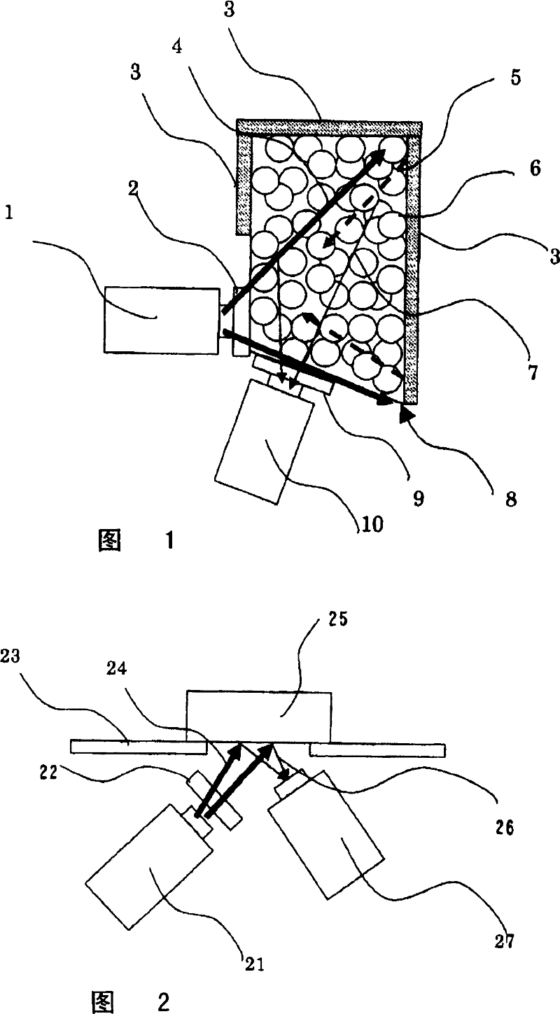
[0067] figure 1 It is a schematic diagram of the X-ray optical system of the fluorescent X-ray analysis apparatus of this invention. exi...


PUM


Abstract

A sample encapsulation container (8) has walls made from an X-ray transmissive material. An X-ray source (1) is placed so that a wall surface is irradiated with a primary X-ray, and a surface different from the surface irradiated with the primary X-ray is placed so as to face an X-ray detector (10). The primary X-ray from the X-ray source (1) is set so that the wall surface, to which the X-ray detector (10) is faced, of the sample encapsulation container can be irradiated with the primary X-ray.

Description

technical field [0001] The present invention relates to a method of irradiating a measurement sample with X-rays once, inducing fluorescent X-rays from the measurement sample, and measuring the energy level and X-ray intensity of the fluorescent X-rays, thereby performing elemental analysis / composition analysis of the sample Fluorescent X-ray analysis device. Background technique [0002] use figure 2 A general conventional fluorescent X-ray analyzer will be described. The measurement sample 25 is arranged above the above-mentioned measurement sample base 23 through the horizontal measurement sample base 23, and the X-ray source 21, the primary filter 22, and the X-ray detector 27 are arranged on the above-mentioned measurement sample. Below the base 23 , the irradiation position of the primary X-ray 24 and the position where the X-ray detector 27 for detecting the fluorescent X-ray 26 faces are the same point. In addition, the sensitivity of fluorescent X-rays originatin...

Claims


Application Information

Patent Timeline
Patent Type & Authority Patents(China)
IPC IPC(8): G01N23/223
CPCG01N23/223G01N2223/076
Inventor 的场吉毅深井隆行高桥正则一宫丰
Owner HITACHI HIGH TECH SCI CORP
Why Eureka
Try Eureka