Variable position cooling apparatus

A device and substrate technology, applied in the field of surface devices

Inactive Publication Date: 2007-10-10
3M INNOVATIVE PROPERTIES CO
View PDF3 Cites 0 Cited by
  • Summary
  • Abstract
  • Description
  • Claims
  • Application Information

AI Technical Summary

Problems solved by technology

[0004] Although heat transfer bags have been used in some cooling systems, the use of heat transfer bags in small electronic devices such as laptop computers has been limited at least in part because of the limited amount of space available within computer cases and their Surface area requirements for effective cooling

Method used


Image

  • Variable position cooling apparatus
  • Variable position cooling apparatus
  • Variable position cooling apparatus

Examples


Embodiment Construction

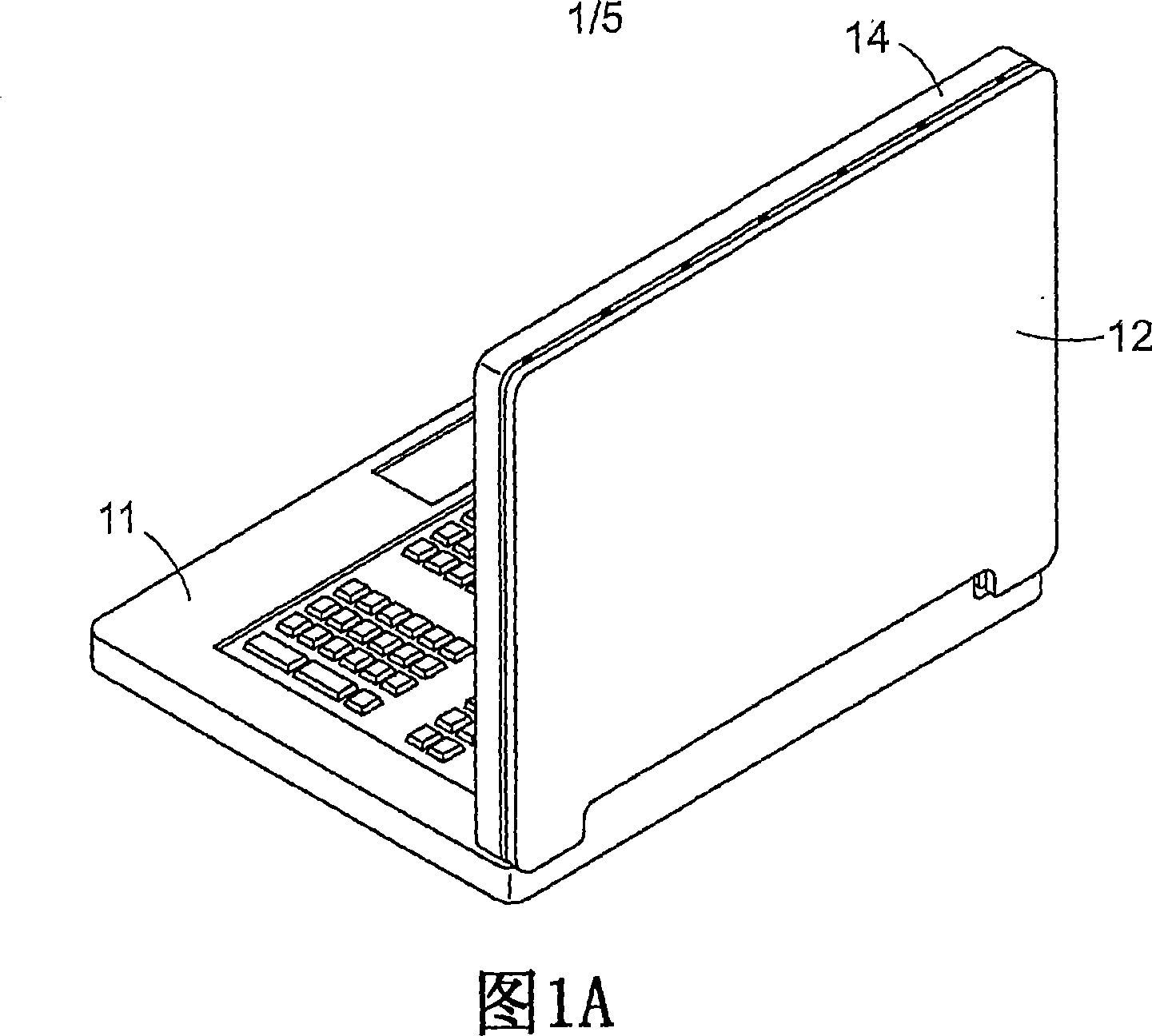
[0026] Figure 1A shows a perspective view of an exemplary embodiment of the present invention positioned on a laptop computer. As shown in FIG. 1A , the movable part 12 is connected to a base 14 . Substrate 14 is the back of the screen of laptop computer 11 . In FIG. 1A , movable member 12 is shown in a closed position in which movable member 12 is adjacent base 14 .

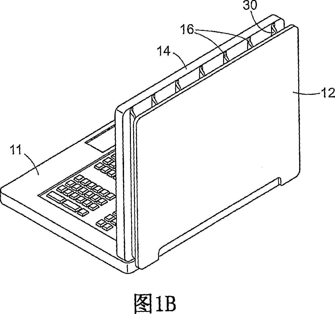
[0027] FIG. 1B shows a perspective view of the exemplary embodiment shown in FIG. 1A with movable member 12 shown in an open position in which movable member 12 is positioned a distance away from base 14 . FIG. 1B also shows a heat transfer bag 30 having a plurality of expansion chambers 16 connecting the movable part 12 to the base 14 . The change in pressure within the expansion chamber 16 causes the movable member 12 to move relative to the base 14 . The movable member 12 generally moves toward the base 14 as the pressure within the expansion chamber 16 decreases. Likewise, movable member 12 generally mov...


PUM


Abstract

A device for cooling a heat-dissipating component comprising an expansion chamber (16) that is expandable between a first volume and a second volume. The expansion chamber adjusts its surface exposure to ambient air according to the operating conditions of the device.

Description

Background technique [0001] As electronic systems become more compact, there is an ongoing desire to increase the rate of heat transfer away from heat dissipating components. While there are many heat transfer techniques conceived for compact devices, it is difficult to provide adequate cooling for the components within the available space within the device. [0002] Although forced air convection has been used in small electronic devices such as laptop computers, the forced air convection method has practical limitations. In forced air systems, the volume of air required to provide adequate cooling often creates undesirable noise levels and can drain battery life in portable devices. [0003] Another method used to cool heat sink components involves the use of fluids in heat transfer bags. Heat transfer bags are typically made of a flexible, durable, air-impermeable film. These bags are filled with a heat-conducting fluid and are usually placed between the heat-generating ...

Claims


Application Information

Patent Timeline
Patent Type & Authority Applications(China)
IPC IPC(8): H05K7/20G06F1/20
CPCG06F1/203G06F1/20H05K7/20
Inventor 菲利普·E·图玛
Owner 3M INNOVATIVE PROPERTIES CO
Why Eureka
Try Eureka