Two levels clamp drill clamping head
A chuck and jaw technology, applied in the field of two-stage clamping drill chucks, can solve the problems of difficult to achieve clamping force, unreliable locking, complex structure, etc., and achieve the effect of simple structure and convenient operation
- Summary
- Abstract
- Description
- Claims
- Application Information
AI Technical Summary
Problems solved by technology
Method used
Image
Examples
no. 1 example
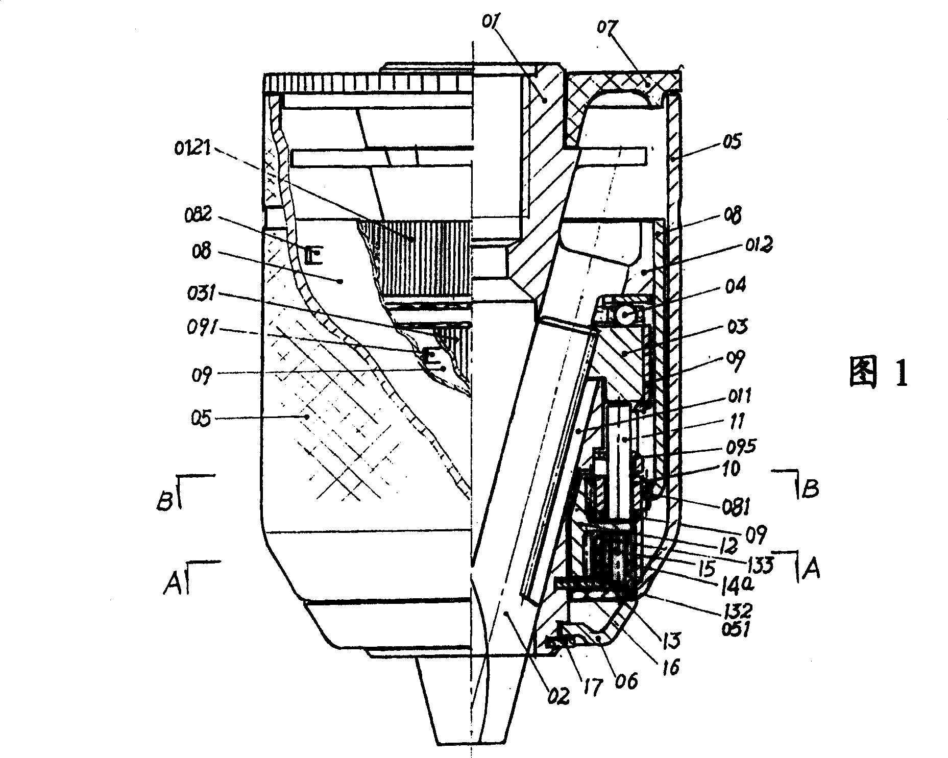
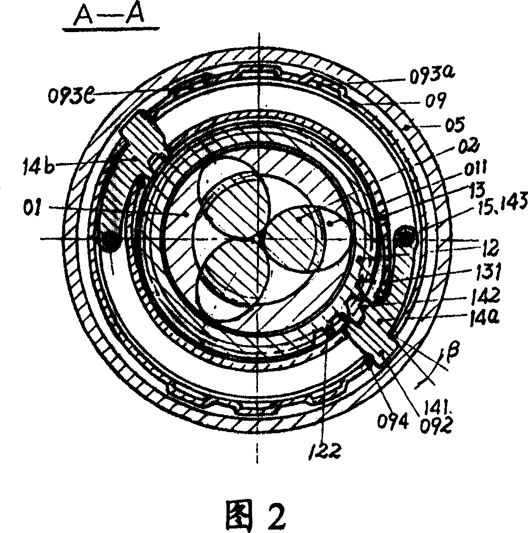
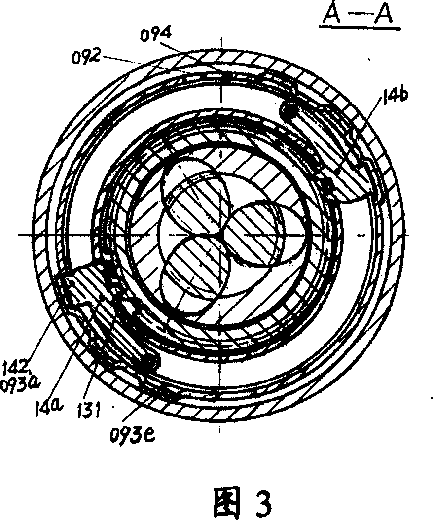
[0106] Referring to Fig. 1, shown is a front partial cross-sectional view of a first embodiment of a chuck according to the present invention. The chuck includes a body 01 located in the center, the body has a longitudinal center axis, the rear end of which is connected with the drive shaft of the power source through a threaded hole or a tapered hole, and the front end forms an accommodating space for a gripping tool handle. The body 01 has a plurality of inclined holes 011 evenly distributed around the central axis of the body. The outer surface of the body 01 also has a bearing platform 012, and the outer surface of the bearing platform 012 has fine teeth 0121.
[0107] In addition, two ring grooves are formed on the outer surface of the front end of the body 01, in which open spring retaining rings 16 and 17 are respectively assembled.
[0108] A plurality of clamping jaws 02 are installed in the oblique hole 011 of the body 01, the rear end of the clamping jaws has an incompl...
no. 2 example
[0129] Referring to Fig. 10, there is shown a front cross-sectional view of a chuck according to a second embodiment of the present invention.
[0130] In the second embodiment, the nut sleeve 19 and the transmission sleeve 20 are combined together to replace the function of the integral structure nut transmission sleeve 09 in the first embodiment.
[0131] FIGS. 11 and 12 show the structure of the nut sleeve 19, and FIGS. 13 and 14 show the structure of the transmission sleeve 20. The lower end of the nut sleeve 19 forms a driving groove 191, and the upper end of the transmission sleeve 20 has a shaft support arm 095. The slot support arm 095 is inserted into the driving slot 191.
[0132]The upper part of the nut sleeve 19 is fixedly sleeved on the nut 03, the lower part is provided with a driving groove 191, and the upper and lower shaft support parts are provided on the transmission sleeve 20 for mounting and supporting the planetary wheel shaft 11 of the planetary wheel 10. T...
no. 3 example
[0141] In the foregoing first and second implementations, the driving pendulum swings in a plane perpendicular to the longitudinal center axis of the body 01. In the third embodiment according to the present invention, the driving pendulum (331) swings in a vertical plane parallel to the longitudinal center axis.
[0142] Fig. 21 is a front cross-sectional view of a chuck according to a third embodiment of the present invention. Referring to FIG. 21, the chuck includes an outer sleeve 05, a nut sleeve 39, a transmission sleeve 30, a gear sleeve 32, and a driving pendulum support sleeve 33.
[0143] Refer to Figure 29, which shows a top view of the jacket 05. The lower end of the jacket is connected to the front cover 06 and has a plurality of grooves 051.
[0144] Referring to Figures 26-28, the structure of the drive pendulum support sleeve 33 is shown. It can be seen from the figure that the lower end of the driving pendulum support sleeve 33 has a plurality of load-bearing keys...
PUM
 Abstract
Description
Claims
Application Information
 - R&D
- Intellectual Property
- Life Sciences
- Materials
- Tech Scout
- Unparalleled Data Quality
- Higher Quality Content
- 60% Fewer Hallucinations
Browse by: Latest US Patents, China's latest patents, Technical Efficacy Thesaurus, Application Domain, Technology Topic, Popular Technical Reports.
© 2025 PatSnap. All rights reserved.Legal|Privacy policy|Modern Slavery Act Transparency Statement|Sitemap|About US| Contact US: help@patsnap.com


