
A head restraint for a motor vehicle

A technology for head protection and motor vehicles, which is applied to the special position of the vehicle, vehicle parts, vehicle seats, etc., can solve the problems of heavy weight, complicated arrangement, high cost, etc., and achieve the effect of cost and weight enhancement

Inactive Publication Date: 2007-10-17
FORD GLOBAL TECH LLC +1
View PDF1 Cites 7 Cited by
  • Summary
  • Abstract
  • Description
  • Claims
  • Application Information

AI Technical Summary

Problems solved by technology

However, the arrangement of the '130 patent is complex, costly, and heavy

Method used


Image

  • A head restraint for a motor vehicle
  • A head restraint for a motor vehicle
  • A head restraint for a motor vehicle

Examples


Embodiment Construction

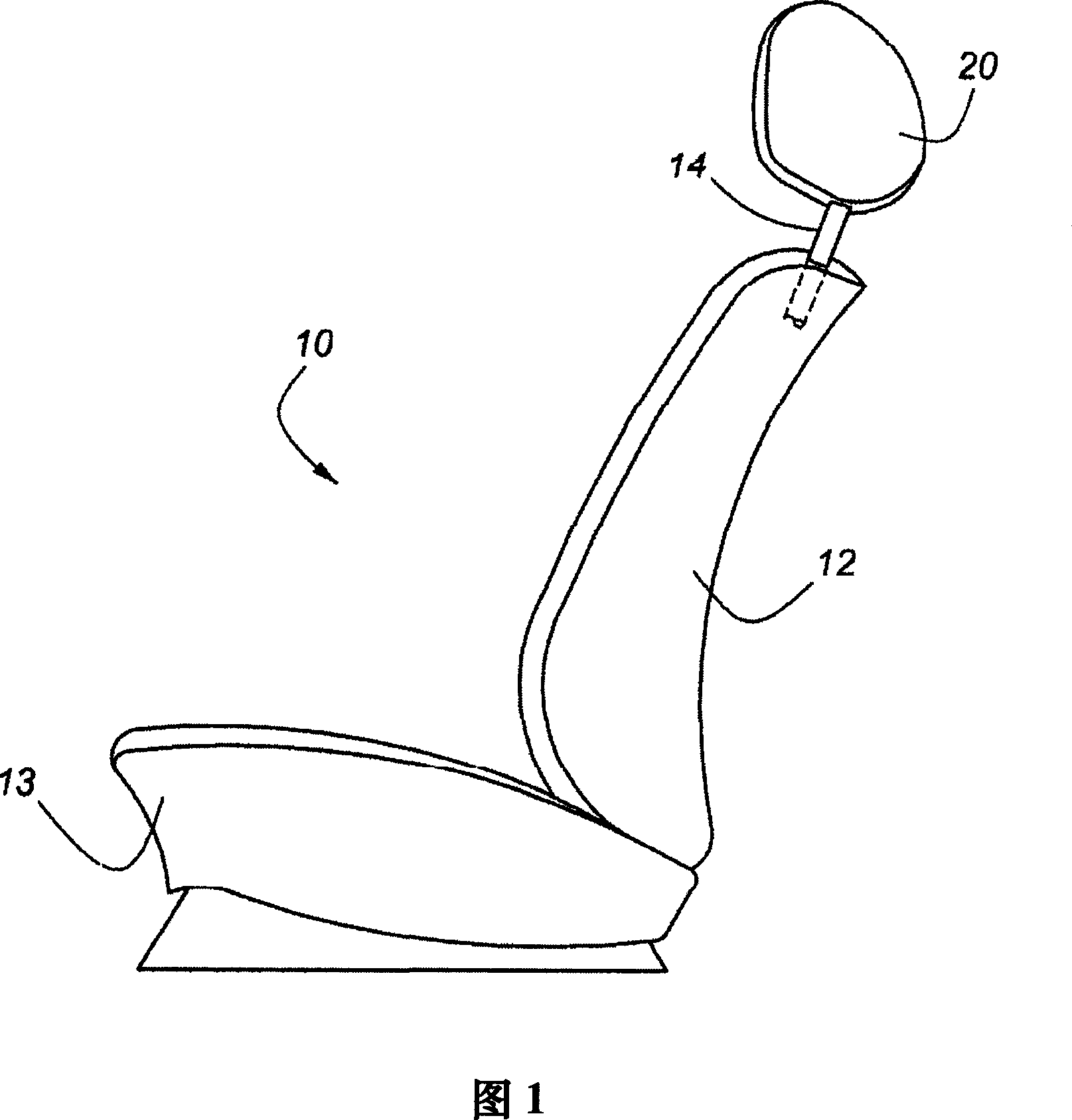
[0018] As shown in FIG. 1 , a seat 10 has a seat cushion 13 and a seat back 12 incorporating a head restraint adjustment mechanism for positioning a head restraint 20 on a mounting bar 14 . FIG. 1 shows one such rod 14 .

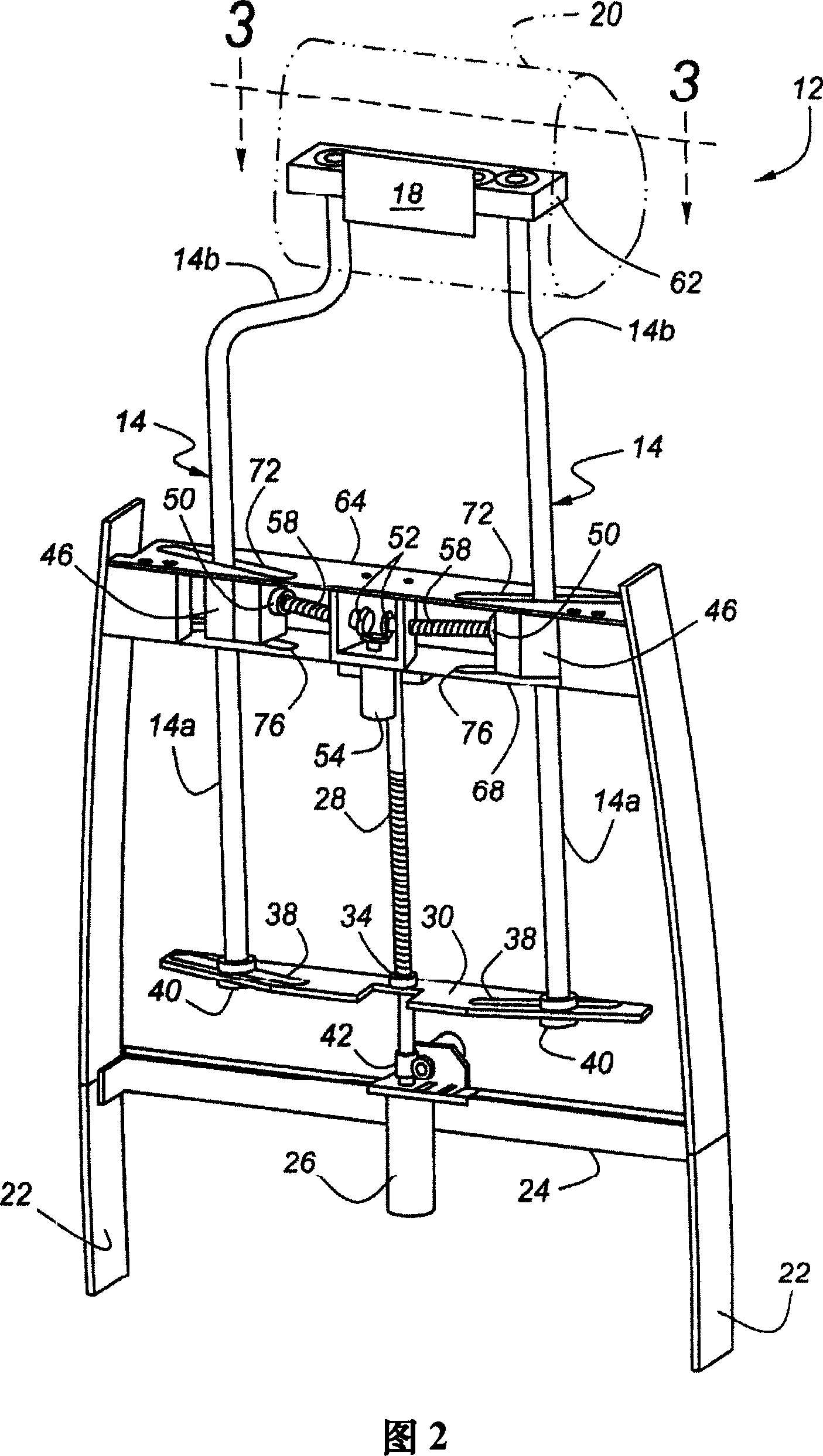
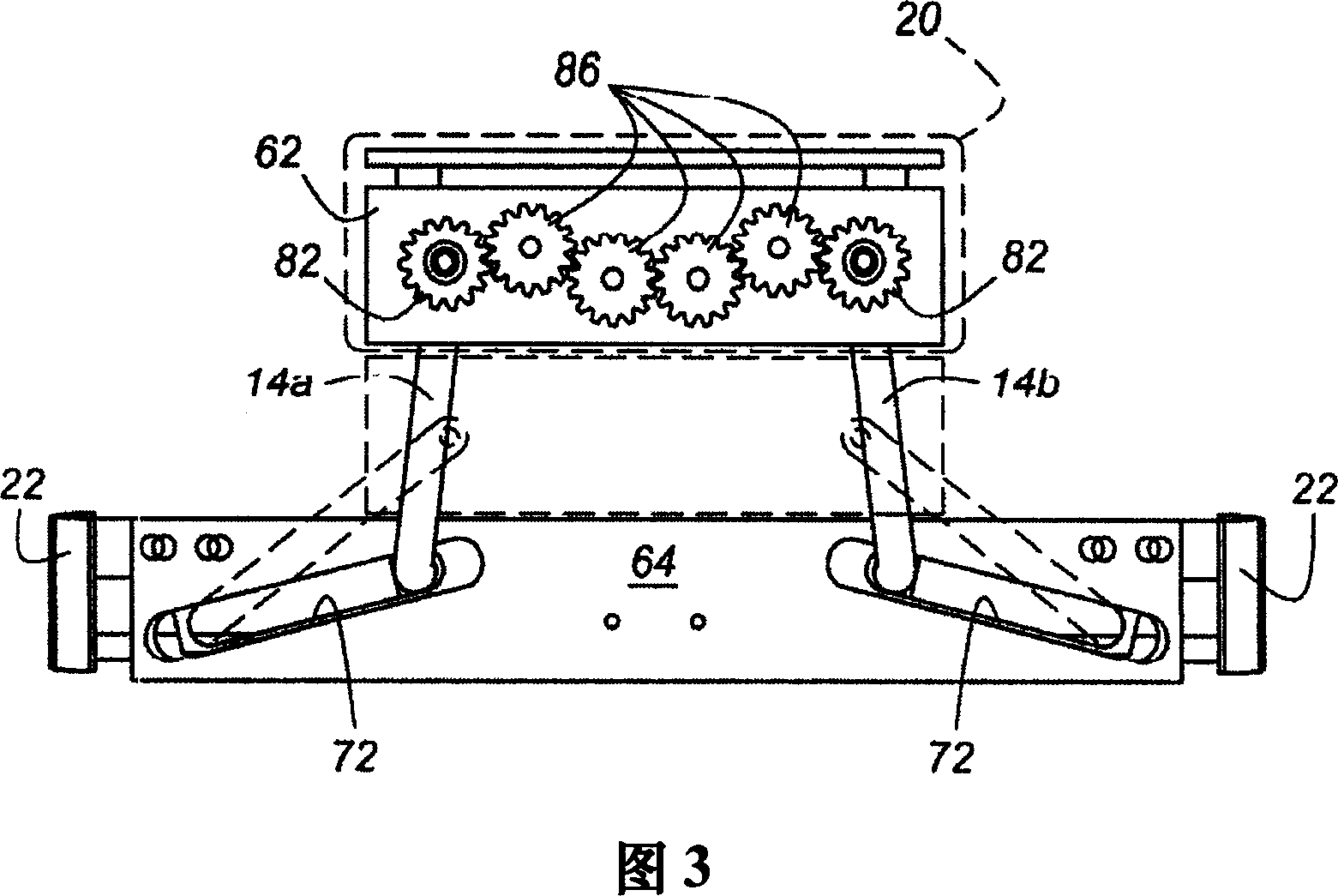
[0019] As shown in FIG. 2, mounting rod 14 provides a basis for the head restraint adjustment mechanism. Each rod 14 has a base 14a, and an eccentric 14b. The base 14 a extends within the seat back 12 . The lowest portion of the fixed pole 14 is mounted on a height control crosspiece 30 . The rod 14a is easily mounted to the height control rail 30 by rod bushings 40 which provide movement in slots 38 in both parts of the height control rail 30. As will be described in more detail below, the slot 38 allows the mounting rod 14 to move laterally, thereby urging the head restraint 20 to move forward and backward.

[0020] Vertical positioning of the mounting rod 14 is accomplished by a lift motor 26 which drives a lead screw 28 via a nut 34 mounted on a heig...


PUM


Abstract

A head restraint system for an automotive vehicle seat includes a headrest carried upon eccentric mounting posts which may be extended telescopically from a seatback and rotated about their base axes so as to reposition the headrest not only vertically, but also horizontally. A sensor mounted in the headrest feeds back the location of an occupant's head to a system controller.

Description

technical field [0001] The invention relates to an automobile head protection system, which comprises a headrest which is driven by a motor to adjust the height and horizontal position of the headrest. Background technique [0002] Adjustable head restraints have been used in motor vehicles for many years. For best results, this head restraint must be properly adjusted. Because it is more difficult to achieve the correct adjustment in the case of manually adjusting the head restraint, motor-driven head restraints have emerged. US Patent No. 6,511,130 discloses a headrest that can be adjusted manually or by means of a motor. However, the arrangement of the '130 patent is complex, costly, and heavy. [0003] The head restraint system for motor vehicles of the present invention occupies a modest volume of packaging, has a moderate weight, and is low in complexity. Contents of the invention [0004] A head restraint system for a motor vehicle includes a plurality of mounti...

Claims


Application Information

Patent Timeline
Patent Type & Authority Applications(China)
IPC IPC(8): B60N2/48
CPCB60N2/4864B60N2/0232B60N2/4829B60N2/829B60N2/865B60N2/02246
Inventor 斯里尼瓦桑·孙达拉拉迦约瑟夫·玛佐爱德华·伯莱
Owner FORD GLOBAL TECH LLC
Learn More