Rotary impeller transmission connection method and connection structure

A technology of rotating impeller and transmission connection, which is applied to the supporting elements of blades, engine elements, machines/engines, etc., can solve the problems of small application range, large rigidity change, unsuitable for high speed, etc., and meets the requirements of wide application range and processing equipment. No, processing equipment requires high effect

Inactive Publication Date: 2007-10-17
杭州杭氧透平机械有限公司
View PDF0 Cites 3 Cited by
  • Summary
  • Abstract
  • Description
  • Claims
  • Application Information

AI Technical Summary

Problems solved by technology

Among them, the key connection method has a gap between the impeller and the shaft, so it is not suitable for high speed; the red sleeve or hydraulic interference connection method has too much rigidity in the interference interval between the impeller and the shaft, and the stiffness outside the interference interval changes greatly, which is easy Broken shaft; the face gear connection method is relatively good, but the processing of the face gear requires expensive processing equipment; the multi-angle shaft connection also requires special processing equipment, and the processing is difficult; methods such as taper friction connection, spline connection, and flange connection are applicable. smaller

Method used


Image

  • Rotary impeller transmission connection method and connection structure
  • Rotary impeller transmission connection method and connection structure
  • Rotary impeller transmission connection method and connection structure

Examples


Embodiment Construction

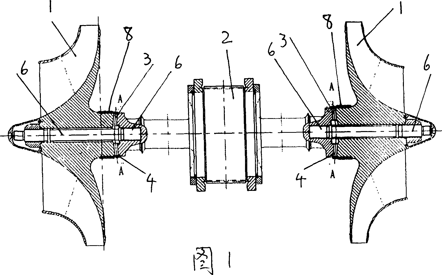
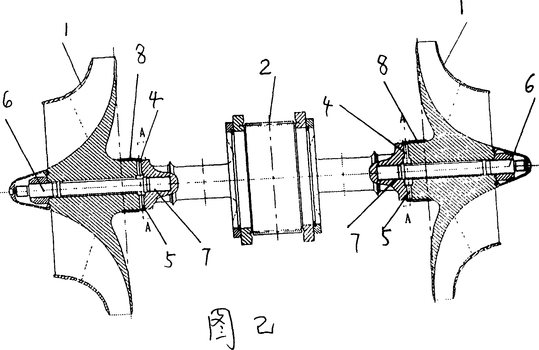
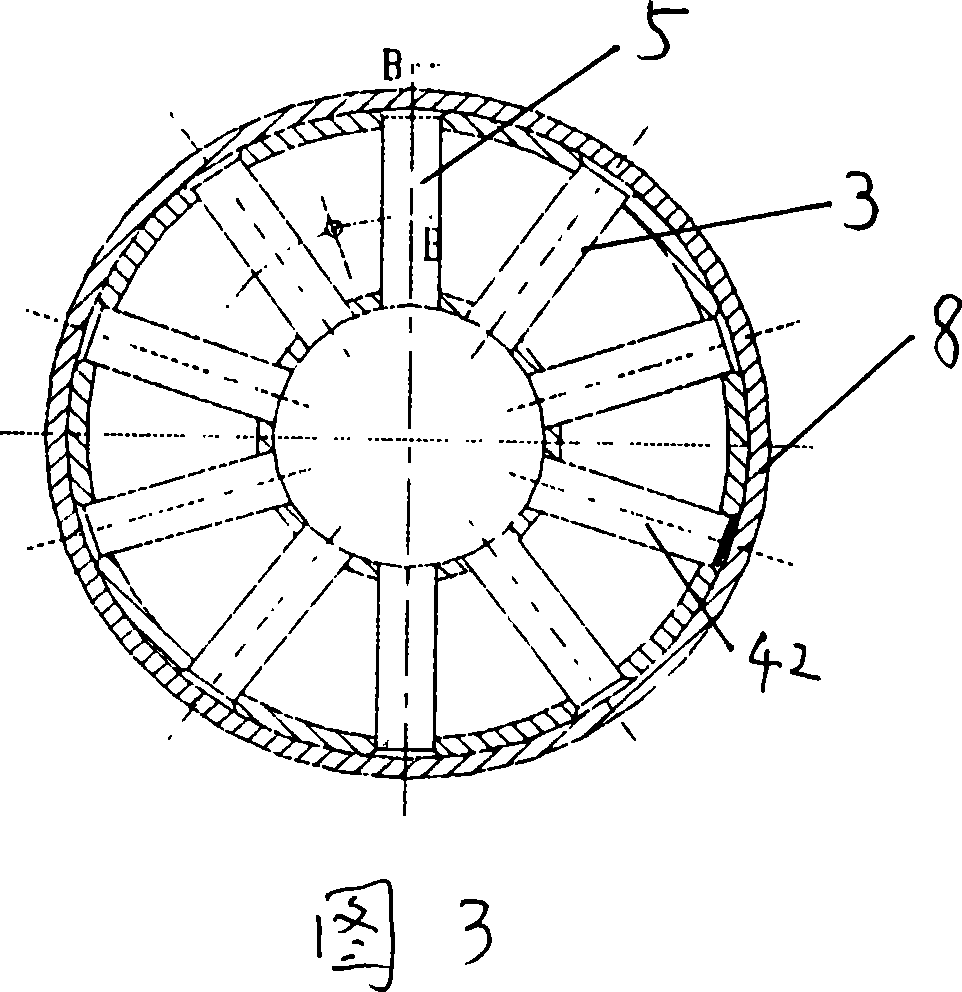
[0021] The present invention will be described in detail below in conjunction with the accompanying drawings: The transmission connection method described in the present invention is: connect the rotating impeller and the transmission shaft with the end face and fix them axially, and insert A plurality of connecting pins are connected to drive the rotating torque, and the rotating impeller is driven to rotate through the connecting pins. The connecting end faces between the rotating impeller and the drive shaft can be connected by end planes or by end cones, and 2-20 joints for transmitting rotational torque are embedded in the form of seams on the connected end faces. connection pin.

[0022] As shown in Fig. 1, the connection structure of the present invention at least includes a rotating impeller 1 and a transmission shaft 2. The rotating impeller 1 and the transmission shaft 2 are connected with the end faces and fixed in the axial direction. There are corresponding 2-20 ...


PUM


Abstract

A transmission connecting method and connecting construction of revolving impeller, the transmission connecting method is that: the revolving impeller is connected by end face and is fixed along axial direction with the transmission shaft, a plurality of tally connecting pins are rabbet jointed on the end face connecting the revolving impeller and the transmission to transmit the revolving torsional force to rotate the revolving impeller driven by the connecting pin; the connecting construction at least comprises a revolving impeller and a transmission shaft, the revolving impeller is connected by end face and is fixed along axial direction with the transmission shaft, the corresponding 2-20 semicircle pin holes arranged radically are provided on the connecting end faces to form a whole pin hole, the connecting pin with tally type end face is provided in the pin hole; the revolving impeller and the transmission shaft are fixablely connected by a drag bolt; the pin hole at least comprises a pin hole communicating with the upper to form an upper through hole and a pin hole with two end positioned in the revolving impeller and the transmission shaft to form a hidden hole, after the corresponding connecting pin is provided in the pin hole, an enclasping ring composed of a sealing axle sleeve is shrinking on tally outer ring of the connecting end face; the invention has characteristics that the structure is simple, the reliability is high, the processing cost is low and the range of applicability is wide, the invention has not high processing facility request and is easy to repair.

Description

technical field [0001] The invention relates to a transmission connection method and connection structure specially used for rotating impellers, especially suitable for the transmission connection method and connection structure between impellers and shafts in high-speed rotating machines such as centrifugal compressors, centrifugal blowers, and centrifugal expanders. , belonging to the field of general machinery technology. Background technique [0002] The connection between the impeller and the shaft is a difficult point in the design and manufacture of fluid machinery. Usually the rotating impeller is sleeved on the transmission shaft, and the transmission connection methods used for the two time mainly include: key connection, red sleeve or hydraulic interference connection, Face tooth connection, polygonal shaft connection, taper friction connection, spline connection, flange connection, etc. Among them, the key connection method has a gap between the impeller and the...

Claims


Application Information

Patent Timeline
Patent Type & Authority Applications(China)
IPC IPC(8): F01D5/02F04D29/28
Inventor 池雪林师建忠
Owner 杭州杭氧透平机械有限公司
Why Eureka
Try Eureka