Connector for solar battery module

A technology of solar cells and connectors, applied in the direction of connections, electrical components, parts of connection devices, etc., can solve problems such as wrong connections, and achieve the effect of preventing reverse connections

Inactive Publication Date: 2007-10-17
SUMITOMO WIRING SYST LTD
View PDF1 Cites 16 Cited by
  • Summary
  • Abstract
  • Description
  • Claims
  • Application Information

AI Technical Summary

Problems solved by technology

Therefore, within each group and between groups there is the possibility of a wrong connection being made between the positive and negative terminals

Method used


Image

  • Connector for solar battery module
  • Connector for solar battery module
  • Connector for solar battery module

Examples


Embodiment 1

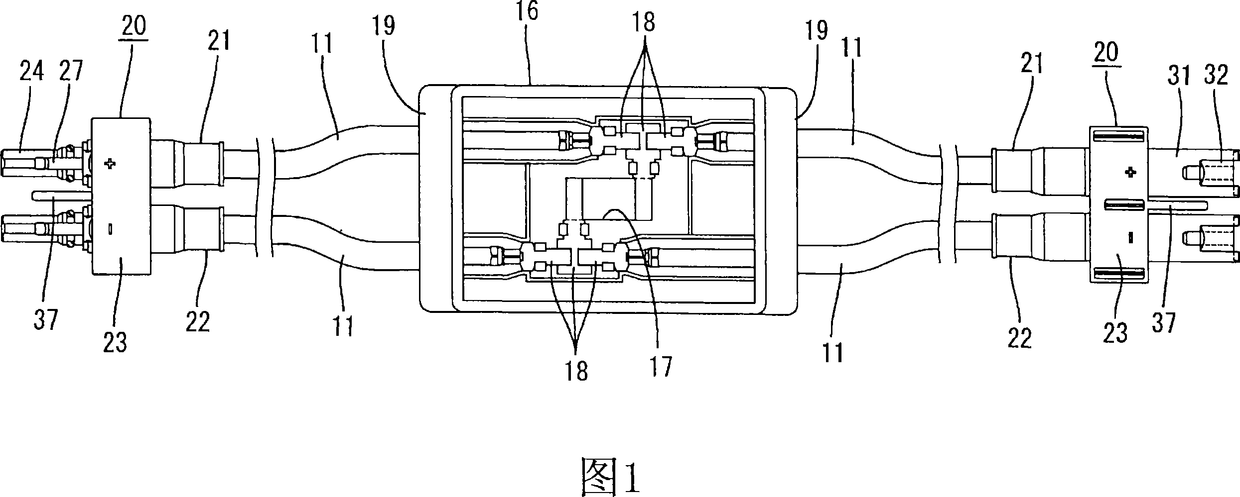
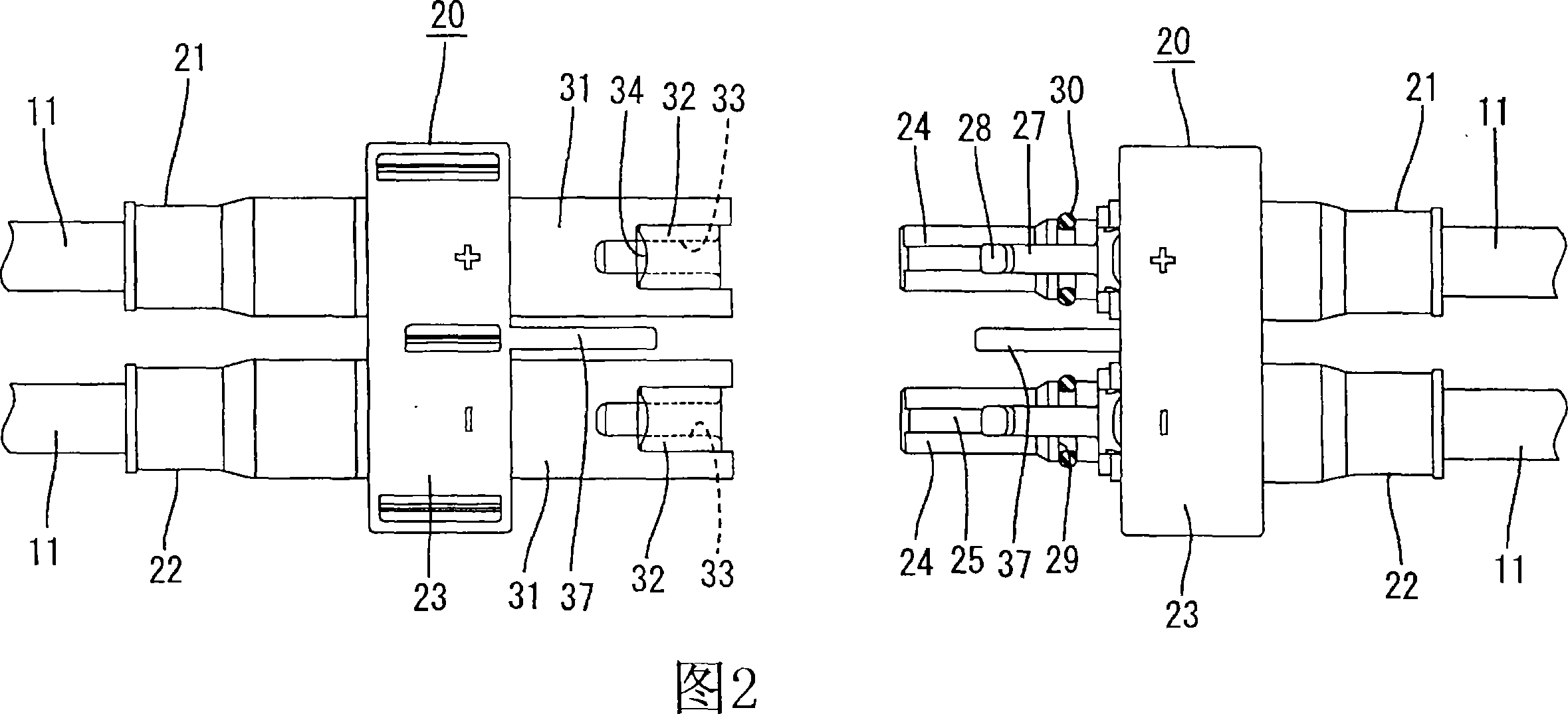
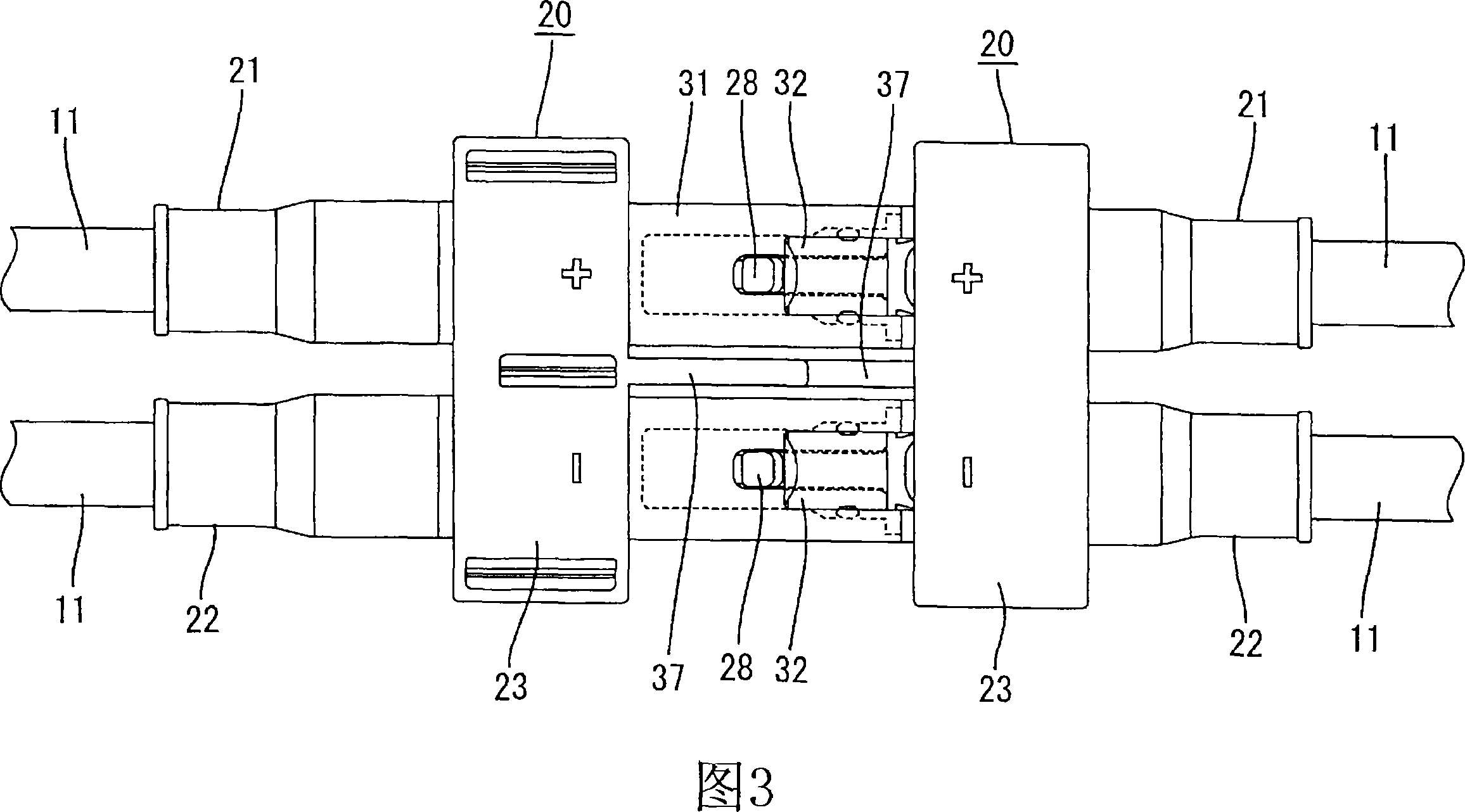
[0064] Embodiment 1 of the present invention will be described below with reference to FIGS. 1 to 8 . In this embodiment, by dividing a pair of positive and negative terminals from the solar cell module 10, two pairs of positive and negative cables 11 are drawn, that is, one pair of positive and negative cables 11 and another pair of positive and negative cables 11, and are integrated A bipolar connector 20 is formed in which the terminal 15 is connected to the end of the drawn-out cable 11. A plurality of solar cell modules 10 are arranged in a matrix form, that is, arranged in alignment with each other along the row and column directions, and are connected to each other in parallel.

[0065] A junction box 16 is attached to the back surface (the surface on the side opposite to the glass surface) of the solar cell module 10 as shown in FIG. 1 . A pair of positive and negative wires (not shown) from the solar cell module 10 are introduced into the junction box 16 through the ...

Embodiment 2

[0081]Embodiment 2 of the present invention will be described below with reference to FIGS. 9 to 12 . The form of the bipolar connector 20 in the second embodiment is different from the bipolar connector in the first embodiment. Embodiment 2 is substantially the same as Embodiment 1 in other respects. The description overlapping with that of Embodiment 1 is omitted, and the same or corresponding structural parts as those of Embodiment 1 are denoted by the same reference numerals.

[0082] In Embodiment 2, the forms of the positive connector 21 and the negative connector 22 constituting the bipolar connector 20 are formed to be different from each other in order to prevent the two poles disposed between a pair of solar cell modules 10 adjacent to each other. The reverse connection between two bipolar connectors 20. More specifically, the structures described below are provided. As shown in the right side of FIG. 9 and FIG. 11, although the protruding portion 26 and the lock ...

Embodiment 3

[0085] Embodiment 3 of the present invention will be described below with reference to FIGS. 13 to 16 . In the third embodiment, the shape of the clamping device 23 in the bipolar connector 20 is different from that of the clamping device in the first embodiment. In other respects, Embodiment 3 is substantially the same as Embodiment 1. Structural parts that are the same as or corresponding to Embodiment 1 are denoted by the same reference numerals.

[0086] Embodiment 3 has the same positive connector 21 and negative connector 22 as Embodiment 1, and a pair of connectors 21 and 22 are installed in a clamping device 23, thereby preventing a pair of solar cell modules adjacent to each other from Reverse connection between two bipolar connectors 20 provided between 10. That is, as shown in FIG. 13 , in the clamping device 23 of Embodiment 3, the clamping device 23 on the plug side and the clamping device 23 on the socket side are identical to each other, and each clamping devi...


PUM


Abstract

Positive and negative poles of a solar cell module (10) are split to take out a pair of positive and negative cables (11), and a two-pole connector (20) where terminals (15) are connected is integrally formed at the forward end of each cable (11). The terminals (15) in the two-pole connector (20) arranged on one side of the solar cell module (10) are plugs for the positive pole and negative pole, and the terminals (15) in the two-pole connector (20) arranged on the other side of the solar cell module (10) are sockets for the positive pole and negative pole. Both two-pole connectors (20) on the plug side and socket side arranged between adjacent solar cell modules (10) are each provided with a projection section (37) as a reverse connection preventing part. The projection sections (37) allow the connection between the connectors (20) when the positive and negative poles of one connector (20) have the same polarilities as those of the other, and prevent the connection when the positive and negative poles of one connector (20) have the different polarities from those of the other.

Description

technical field [0001] The invention relates to a solar cell module connector for connecting a plurality of solar cell modules. Background technique [0002] The solar power generation system supplies direct current from a solar panel installed on the roof to each electric appliance via a device such as an inverter. The solar cell panel is composed of a plurality of solar cell modules connected to each other via connectors connected to ends of cables. [0003] A solar power generation system formed by connecting a plurality of solar cell modules in parallel with each other is known (for example, see Patent Document 1 shown below). This type of solar power generation system has a structure in which, as shown in FIG. 17A, a pair of positive and negative cables 2 branched from a pair of positive and negative terminals of a solar cell is drawn out, the positive connector 3 and the negative connector 4 are connected to the end of the cable 2, and, as shown in FIG. 17B, the posi...

Claims


Application Information

Patent Timeline
Patent Type & Authority Applications(China)
IPC IPC(8): H01R13/64H01R13/639H01L31/042
CPCH02S40/34H01R13/642H01R13/6273Y02E10/50H01L31/02008H01L31/0485
Inventor 东小园诚内藤和树
Owner SUMITOMO WIRING SYST LTD
Why Eureka
Try Eureka