
Current-limiting protection circuit

A current-limiting protection and circuit technology, which is applied in the field of current-limiting protection circuits, can solve the problems of being unable to be used as a sensitive protection device, increasing the cost of relays, and slow response to overcurrent of fuses, etc., and achieves easy restoration of the original circuit, low cost, and practicality strong effect

Inactive Publication Date: 2018-06-29
CHONGQING CHUANYI AUTOMATION
View PDF5 Cites 0 Cited by
  • Summary
  • Abstract
  • Description
  • Claims
  • Application Information

AI Technical Summary

Problems solved by technology

[0011] (1) The overcurrent response of the fuse is relatively slow and cannot be used as a sensitive protection device;
[0012] (2) Relays and current limiting devices will cause an increase in cost

Method used


Image

  • Current-limiting protection circuit

Examples


Embodiment Construction

[0032] Embodiments of the present invention are described below through specific examples, and those skilled in the art can easily understand other advantages and effects of the present invention from the content disclosed in this specification. The present invention can also be implemented or applied through other different specific implementation modes, and various modifications or changes can be made to the details in this specification based on different viewpoints and applications without departing from the spirit of the present invention.

[0033] It should be noted that the diagrams provided in this embodiment are only schematically illustrating the basic idea of ​​the present invention, and only the components related to the present invention are shown in the diagrams rather than the number, shape and shape of the components in actual implementation. Dimensional drawing, the type, quantity and proportion of each component can be changed arbitrarily during actual impleme...


PUM


Abstract

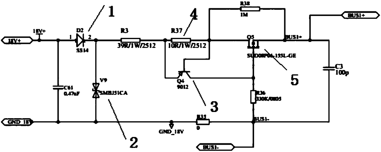
The invention provides a current-limiting protection circuit, which comprises a rectifier diode, a voltage stabilizing diode, a PNP triode, a resistor and a PMOS transistor, wherein a positive electrode of the rectifier diode is connected with an input end of the current-limiting protection circuit, and a negative electrode of the rectifier diode is connected with a positive electrode of the voltage stabilizing diode; a negative electrode of the voltage stabilizing diode is connected with an output end of the current-limiting protection circuit; an emitting electrode of the PNP triode is connected with the negative electrode of the rectifier diode, a collecting electrode of the PNP triode is connected with a grid electrode of the PMOS transistor, and a base electrode of the PNP triode is connected with a drain electrode of the PMOS transistor; a source electrode of the PMOS transistor is connected with the output end of the current-limiting protection circuit; and two ends of the resistor are respectively connected with the emitting electrode of the PNP triode and the drain electrode of the PMOS transistor. The current-limiting protection circuit has the characteristics of high-speed disconnection and easy recovery, and can provide current-limiting protection for any DC circuits.

Description

technical field [0001] The invention relates to the technical field of electronic circuits, in particular to a current limiting protection circuit. Background technique [0002] Components in electronic circuits have their operating currents. When the current in the circuit exceeds the working current, it will cause damage to the components, and it will not work normally, and it will cause a short circuit and cause the circuit to burn out. Therefore, it is very necessary to carry out current limiting protection on the circuit. [0003] In the prior art, the following methods are usually used for current limiting protection of the circuit: [0004] (1) Using self-recovery fuse [0005] Resettable fuse is a kind of overcurrent electronic protection element, which is made of high molecular organic polymer under the conditions of high pressure, high temperature and vulcanization reaction, after adding conductive particle materials, and then processed by special technology. T...

Claims


Application Information

Patent Timeline
Patent Type & Authority Applications(China)
IPC IPC(8): H02H3/08
CPCH02H3/08
Inventor 张仪
Owner CHONGQING CHUANYI AUTOMATION
Learn More