Spiral mechanism for horizontal centrifugal machine

A decanter centrifuge and screw mechanism technology, applied in the field of screw mechanism, can solve the problems of friction between the screw and the feeding pipe, reduced sedimentation and separation effect, wear of the screw outlet, etc., so as to improve work efficiency, reduce maintenance costs, extend the The effect of working life

A decanter centrifuge and screw mechanism technology, applied in the field of screw mechanism, can solve the problems of friction between the screw and the feeding pipe, reduced sedimentation and separation effect, wear of the screw outlet, etc., so as to improve work efficiency, reduce maintenance costs, extend the The effect of working life

CN101058085AInactive Publication Date: 2007-10-24SHANGHAI CENTRIFUGE INST

Image

  • Spiral mechanism for horizontal centrifugal machine
  • Spiral mechanism for horizontal centrifugal machine

Examples


Embodiment Construction

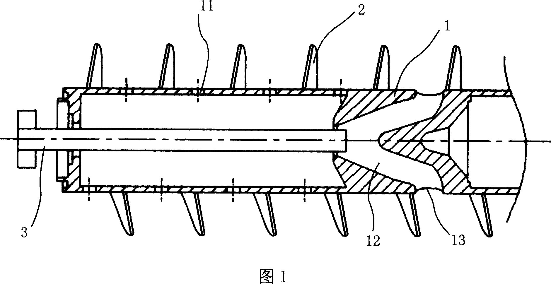
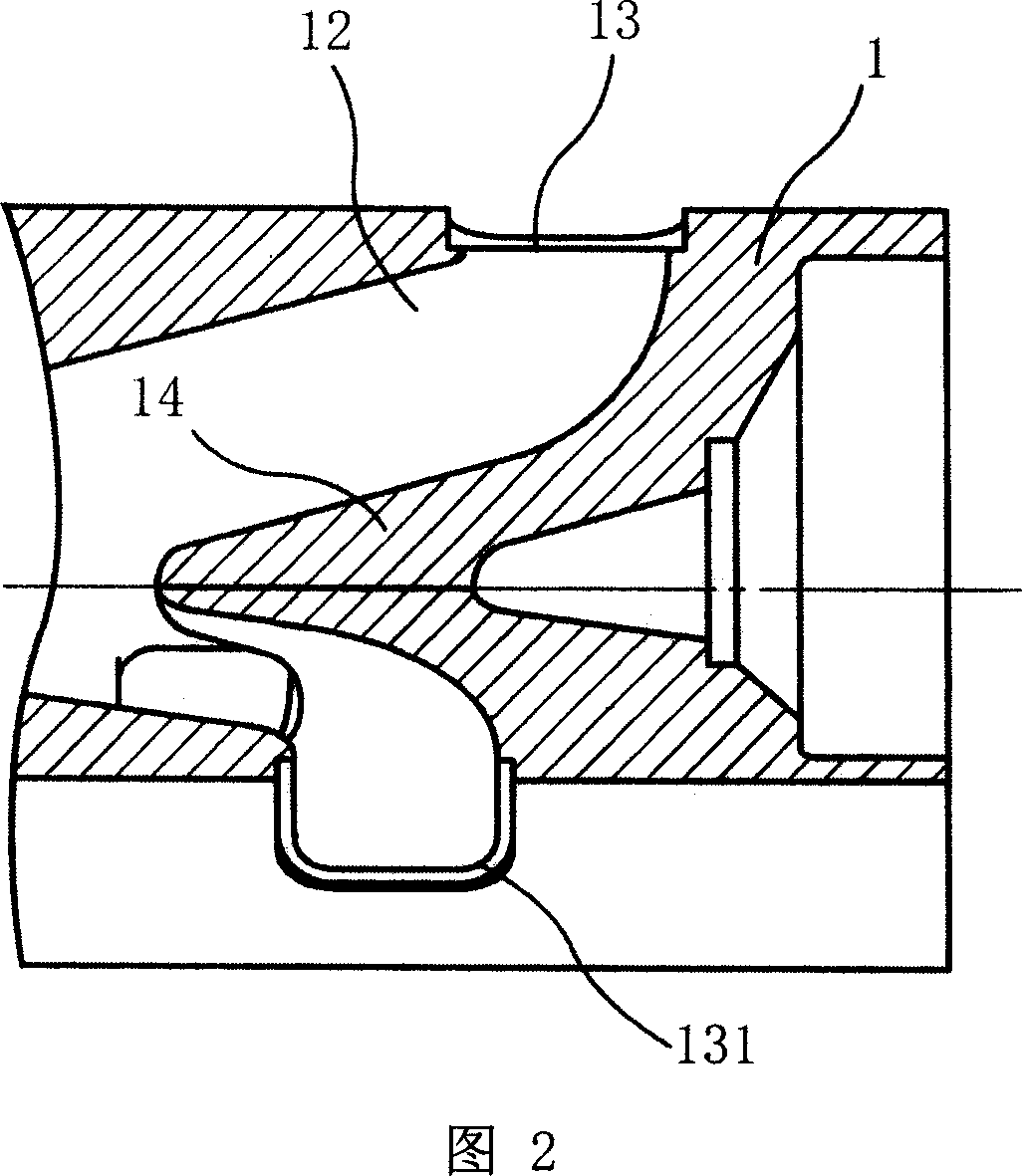
[0012] The screw mechanism of the decanter centrifuge as shown in Figure 1 and Figure 2 includes a screw blade 2 and a screw cylinder 1, and a plurality of leakage holes 11 are arranged on the circumferential wall of the spiral cylinder 1, corresponding to the outlet of the feed pipe 3 of the centrifuge. The circumferential wall of the spiral barrel 1 of the section is provided with mutually symmetrical 2-3 discharge ports 13, and a single discharge port 13 of the screw feed cavity is connected with an independent channel 12, and the discharge port 13 and the independent channel 12 are in common. The spiral feeding chamber structure is formed, each independent channel 12 is connected with the feeding chamber cavity, and the three outlets 13 are arranged at intervals of 120 degrees from each other with the axis of the spiral as the symmetrical center, and the three outlets of the spiral feeding chamber A conical acceleration bucket 14 is arranged between the symmetrical discharg...


PUM


Abstract

A horizontal centrifugal spiral machine comprises the spiral cylinder with over one leaking holes on the wall and the spiral vane, feeding mouth of the centrifugal corresponding to the spiral cylinder having at least two symmetrical material outlet, each connected to an independent channel and formed into the spiral feeding cavity structure, each channel connected with the said cavity, with outlet of the independent channel having bigger arc angle, the radius being one third or one half of the spiral cylinder diameter, with reduced friction and collision, and damage to the separation, being able to extend the durability of the machine, improved in working efficiency and reduced in maintenance cost.

Description

technical field [0001] The invention relates to a screw mechanism of a decanter centrifuge, especially suitable for a decanter centrifuge with a large aspect ratio. Background technique [0002] The decanter centrifuge is a horizontal screw discharge decanter centrifuge. At present, it has been widely used in municipal sludge dewatering, water plant sludge dewatering, industrial and agricultural wastewater treatment, solid-liquid separation and dehydration in chemical, food, pharmaceutical and other industries. For decanter centrifuges, the longer the settling zone, the greater the aspect ratio, the better the separation effect, but the greater the shaft power; in actual use, decanter centrifuges with different length-to-diameter ratios will be selected according to different media properties, but When a decanter centrifuge with a large length-to-diameter ratio handles materials with a large flow rate or a large specific gravity, the material often flows back from the gap be...

Claims


Application Information

Patent Timeline
24 Oct 2007
Publication
CN101058085A
IPC
B04B3/04; B04B11/02
Inventors
阮智伟; 孙祥建