

Automatic winder
A winder, automatic technology, used in rewinding machines, textiles and papermaking, conveying filamentous materials, etc., can solve problems such as limited, achieve the effect of eliminating broken ends or fluff, and reducing tension fluctuations
- Summary
- Abstract
- Description
- Claims
- Application Information
AI Technical Summary
Problems solved by technology
Method used
Image

Examples
Embodiment 1
[0029] Example 1 is the case from the unwinding of the yarn supplying bobbin to the final rotation of the yarn supplying bobbin.
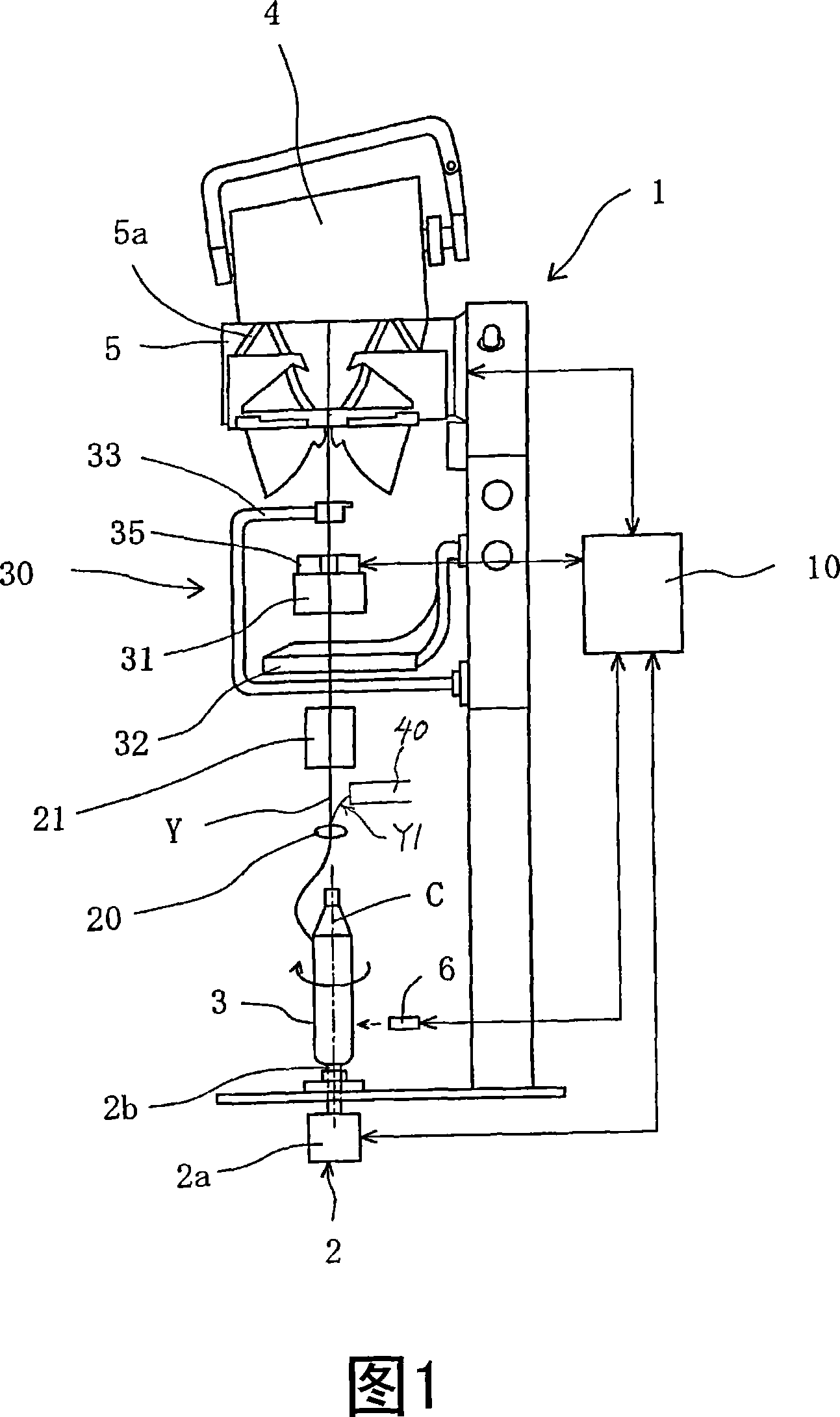
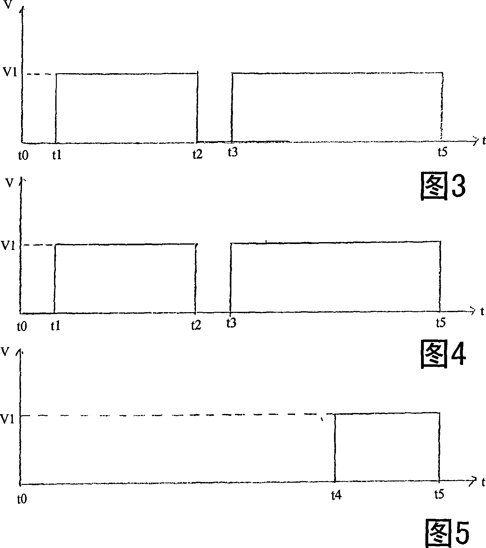
[0030] FIG. 3 shows a drive timing chart of the drum 5, and FIG. 4 shows a drive timing chart of the bobbin rotating mechanism 2. As shown in FIG. At this time, after supplying a new yarn feeding bobbin (replacement bobbin) to the winding unit (t0), it is spliced with the yarn on the package side, and winding is restarted (t1). The drum 5 rotates at the winding speed V1, and the yarn supplying bobbin rotating mechanism 2 also rotates at the unwinding speed v1.
[0031] When the yarn clearer 35 detects a yarn defect such as a slub yarn, the running yarn is forcibly cut by a cutter built into the yarn clearer or a separate cutter based on a yarn defect detection signal. When the yarn is cut, since the yarn clearer turns the yarn traveling signal (FW signal) "off", the driving of the drum 5 is stopped (t2). At this time, if the rotary drive mechan...
Embodiment 2
[0035]Example 2 is a case where the rotary drive mechanism 2 is stopped during the period from the start of winding until the remaining amount of yarn is about 1 / 3, and the rotary drive mechanism 2 is driven based on the detection of the distance sensor 6 to rotate the yarn supplying bobbin 3 at a high speed. . In Fig. 5, during the period from the start of winding (t0) to about 1 / 3 of the remaining amount of yarn, even if yarn cutting, splicing, etc. occur midway, the rotary drive mechanism 2 is stopped, and the remaining amount of yarn is about 1 / 3. At 1 / 3 time (t4), the rotary drive mechanism 2 is driven to rotate the bobbin in the unwinding direction. The remaining yarn amount of the bobbin is detected by the aforementioned sensor 6 (FIG. 1) or the like.
Embodiment 3
[0036] Example 3 is a case where the bobbin rotation speed is controlled in accordance with the increase in the winding diameter of the package.
[0037] If the diameter of the package rotates driven by the surface contact of the drum 5 becomes larger, it may fail to follow the rotation of the drum 5 and cause slippage when rewinding after splicing, or may damage the surface of the yarn layer. , in order to prevent this situation, the speed at which the package rotates and starts should be controlled according to the size of the package diameter. At this time, it is also necessary to change the rotational speed of the yarn supplying bobbin according to the diameter of the package in order not to cause slack in the yarn.
[0038] FIG. 6 is a linear diagram of the rotational speed of the package, and FIG. 7 is a linear diagram of the rotational speed of the bobbin corresponding to FIG. 6 .
[0039] In Fig. 6, since there are few yarn layers at the beginning of winding onto a ne...
PUM
 Abstract
Description
Claims
Application Information