

Heat-insulating housings and preparation method thereof
A technology of a thermal insulation box and a manufacturing method, which are applied in the field of thermal insulation boxes and their manufacturing, can solve the problems of poor outer box, deformation, bad local deformation of rigid polyurethane foam outer box, etc., and achieve the effect of restraining the usage amount.
- Summary
- Abstract
- Description
- Claims
- Application Information
AI Technical Summary
Problems solved by technology
Method used
Image

Examples
Embodiment 1
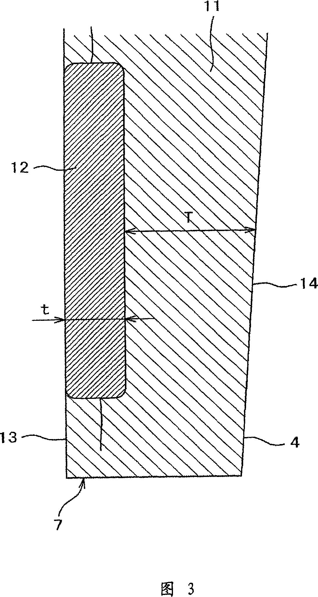
[0044] Example 1 in Table 1 is an example in which the thickness t of the vacuum insulation panel 12 is set to 5 mm, and the flow thickness T of the rigid polyurethane foam 11 is set to 10 mm (T=2t). In this Example 1, when the rigid polyurethane foam 11 is foamed, no unfilled voids are generated near the corresponding portion, and the thermal conductivity is 18.7 mW / m·K, subtracting the central portion from the overall density The numerical value of the density is 3.2, and the rigid polyurethane foam 11 itself is a numerical value not greatly different from that of Conventional Example 1. It is considered that the flow of the rigid polyurethane foam 11 proceeds smoothly, and the material properties inherent in the rigid polyurethane foam 11 are obtained.
Embodiment 2
[0046] Example 2 in Table 1 is an example in which the thickness t of the vacuum insulation panel 12 is set to 5 mm, and the flow thickness T of the rigid polyurethane foam 11 is set to 15 mm (T>2t). In this Example 2, when the rigid polyurethane foam 11 is foamed, no unfilled voids are generated near the corresponding portion, and the thermal conductivity is 18.5 mW / m·K, subtracting the central portion from the overall density The numerical value of the density was 3.4, which was a numerical value not significantly different from Conventional Example 1. This is considered to allow the flow of the rigid polyurethane foam 11 to proceed smoothly, and to obtain the material properties inherent in the actual rigid polyurethane foam 11 .
Embodiment 3
[0050] Example 3 in Table 1 is an example in which the thickness t of the vacuum insulation panel 12 is set to 10 mm, and the flow thickness T of the rigid polyurethane foam 11 is set to 20 mm (T=2t). In this Example 3, when the rigid polyurethane foam 11 is foamed, no unfilled voids are generated near the corresponding portion, and the thermal conductivity is 18.6 mW / m·K, subtracting the central portion from the overall density The numerical value of the density is 3.5, and the rigid polyurethane foam 11 itself is a numerical value not significantly different from that of Conventional Example 1. It is considered that the flow of the rigid polyurethane foam 11 proceeds smoothly, and the material properties inherent in the rigid polyurethane foam 11 are obtained.
PUM
| Property | Measurement | Unit |
|---|---|---|
| Density | aaaaa | aaaaa |
| Compressive strength | aaaaa | aaaaa |
| Pressure | aaaaa | aaaaa |
Abstract
Description
Claims
Application Information