Illuminator and method for producing such illuminator

A light emitter and light source technology, applied in the field of light emitters, to achieve the effect of maximizing optical efficiency

Active Publication Date: 2007-10-24
LUMILEDS HLDG BV
View PDF1 Cites 16 Cited by
  • Summary
  • Abstract
  • Description
  • Claims
  • Application Information

AI Technical Summary

Problems solved by technology

[0004] However, although the solution proposed in US2004 / 0080939 partially improves the optical efficiency, the light emitted from the LED is still absorbed by, for example, the substrate and the boundaries between the pads

Method used


Image

  • Illuminator and method for producing such illuminator
  • Illuminator and method for producing such illuminator
  • Illuminator and method for producing such illuminator

Examples


Embodiment Construction

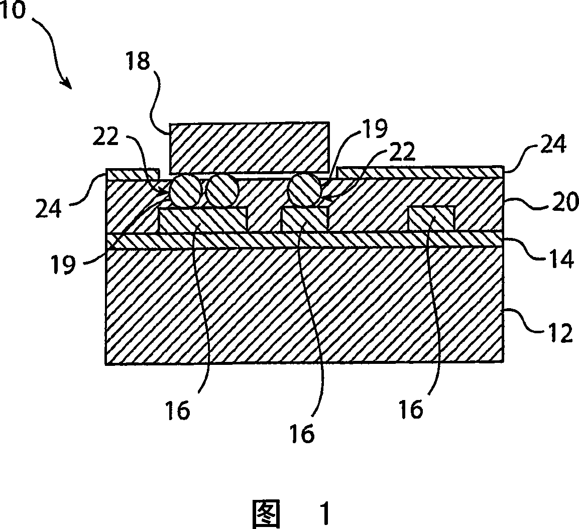
[0020] 1 shows a light emitter 10 according to an embodiment of the present invention. The light emitter 10 includes a substrate 12, such as a silicon substrate, a dielectric layer 14 formed on the substrate 12, and a structure formed on the dielectric layer 14. conductive layer 16. The structured conductive layer 16 covers part of the substrate surface and forms conductive tracks on which the LED chips 18 with contact pads 19 are mounted. Thus, through the structured conductive layer 16, the LED chip 18 can be electrically connected to an external circuit. The LED chip 18 in FIG. 1 is flip-chip mounted, and the conductive layer 16 preferably comprises Cu.

[0021] The substrate with the LED chips 18 is preferably covered by optical elements (not shown), such as optical lenses or collimators. Likewise, the bottom side of substrate 12 is preferably soldered to a heat sink (not shown) for heat dissipation.

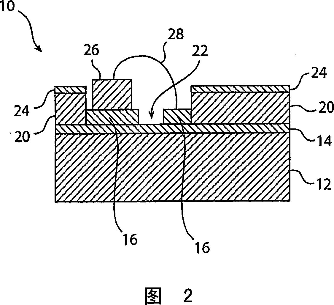
[0022] According to the invention, an insulating layer (20) is furth...


PUM


Abstract

The present invention relates to an illuminator (10) comprising a substrate (12), a structured conductive layer (16) applied to one surface of the substrate, and at least one light source (18, 26) connected to the structured conductive layer. The illuminator is characterized in that it further comprises an unstructured reflective layer (24) applied on top of said structured conductive layer, which unstructured reflective layer has an essentially continuous extension at least in a surrounding of the at least one light source. Due to the unstructured reflective layer, the optical efficiency of the illuminator can be improved. The invention also relates to a method for producing such illuminator.

Description

technical field [0001] The present invention relates to a light emitter comprising: a substrate, a structured conductive layer formed on one surface of the substrate, and at least one light source connected to the structured conductive layer. The invention also relates to a method of manufacturing such a light emitter. Background technique [0002] Light emitting diode (LED) based emitters, especially multi-chip LED modules are being widely developed. However, with LEDs, there is a problem that the directionality and uniformity of the light emitted from the LED chip is very poor, which has a negative impact on the optical efficiency of the LED module. [0003] This problem is addressed, for example, in US Patent Application No. 2004 / 0080939, which discloses a light emitter comprising a light source, such as an LED, mounted on a substrate, and a lens covering the light source. The substrate includes a plurality of pads of conductive and reflective material, where each pad i...

Claims


Application Information

Patent Timeline
IPC IPC(8): H01L33/00H01L33/60
CPCH01L33/60H01L2224/16225H01L2224/48091H01L2224/48227H01L2224/14H01L2924/00014
Inventor C·G·A·霍伦A·C·J·C·范登阿克维肯C·F·J·鲁特杰斯K·范奥斯M·A·德萨姆伯T·C·特鲁尔尼特
Owner LUMILEDS HLDG BV
Why Eureka
Try Eureka