
Light emitting diode structure

A technology of light emitting diodes and conductive structures, applied in electrical components, circuits, semiconductor devices, etc., can solve the problem of unsatisfactory light extraction efficiency, and achieve the effect of improving light extraction efficiency and increasing reflective area.

Active Publication Date: 2015-02-11
GENESIS PHOTONICS
View PDF6 Cites 5 Cited by
  • Summary
  • Abstract
  • Description
  • Claims
  • Application Information

AI Technical Summary

Problems solved by technology

Although the above method can increase the light extraction efficiency of LEDs, its light extraction efficiency cannot meet the current requirements for high light extraction efficiency.

Method used


Image

  • Light emitting diode structure
  • Light emitting diode structure
  • Light emitting diode structure

Examples


Embodiment Construction

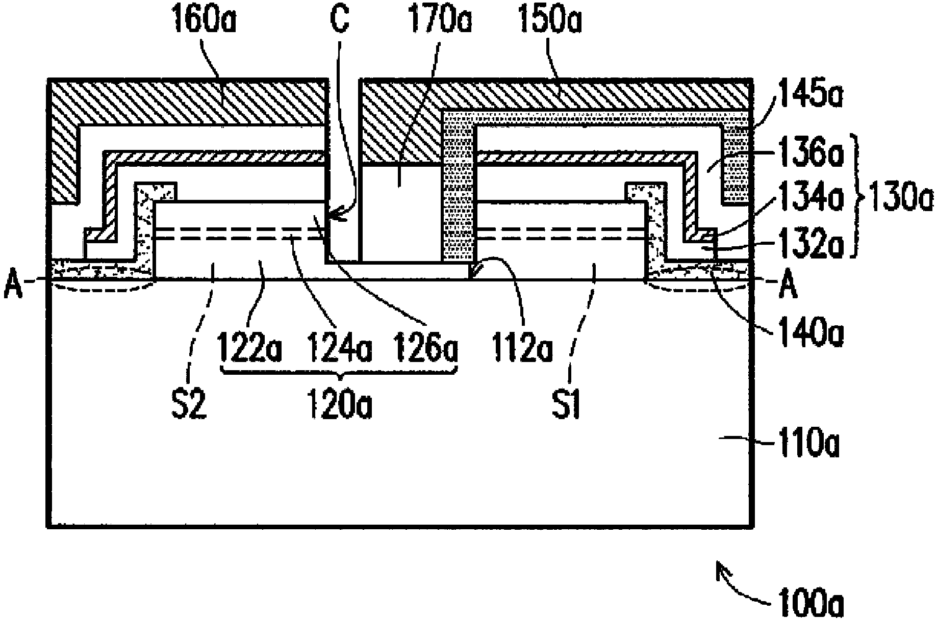
[0048] figure 1 It is a schematic cross-sectional view of a light emitting diode structure according to an embodiment of the present invention. Please refer to figure 1 , in this embodiment, the light emitting diode structure 100a includes a substrate 110a, a semiconductor epitaxial layer 120a and a reflective conductive structure layer 130a. The semiconductor epitaxial layer 120a is disposed on the substrate 110a, and exposes a part of the substrate 110a ( figure 1 in the imaginary circle A). The reflective conductive structure layer 130a is disposed on the semiconductor epitaxial layer 120a, wherein the reflective conductive structure layer 130a covers part of the semiconductor epitaxial layer 120a and the portion of the substrate 110a exposed by the semiconductor epitaxial layer 120a.

[0049] More specifically, in this embodiment, the substrate 110a is, for example, a sapphire substrate, but not limited thereto, wherein the substrate 110a has an upper surface 112a. The...


PUM


Abstract

The invention provides a light emitting diode structure. The light emitting diode structure comprises a substrate, a semiconductor epitaxial layer and a reflection conducting structure layer. The semiconductor epitaxial layer is configured on the substrate and exposes a part of the substrate. The reflection conducting structure covers a part of the semiconductor epitaxial layer and the portion, which is exposed by of the semiconductor epitaxial layer, of the substrate.

Description

technical field [0001] The present invention relates to a semiconductor structure, and more particularly to a light emitting diode structure. Background technique [0002] Generally speaking, when making LED wafers, the substrate is usually provided first, and the epitaxial structure is formed on the substrate by epitaxial growth method, and then electrodes are arranged on the epitaxial structure to provide electric energy, so that light can be emitted by using the photoelectric effect . Afterwards, a plurality of criss-cross cutting lines are formed in the epitaxial structure by using a lithographic etching technique. Wherein, each two adjacent vertical dicing lines and two adjacent horizontal dicing lines together define a light emitting diode crystal grain. Afterwards, the subsequent grinding and dicing process is performed to divide the LED wafer into many LED crystal grains, and then complete the production of LEDs. [0003] In order to increase the light extraction ...

Claims


Application Information

Patent Timeline
Patent Type & Authority Applications(China)
IPC IPC(8): H01L33/38H01L33/20
CPCH01L33/20H01L33/38
Inventor 黄逸儒罗玉云吴志凌黄靖恩丁绍滢
Owner GENESIS PHOTONICS
Learn More