Light-emitting element and display device

a technology of light-emitting elements and display devices, which is applied in static indicating devices, instruments, non-linear optics, etc., can solve the problems of deterioration of light extraction efficiency, mainly affecting the light extraction efficiency, so as to achieve high light extraction efficiency and high reliability

Inactive Publication Date: 2007-04-10
SEMICON ENERGY LAB CO LTD
View PDF3 Cites 45 Cited by
  • Summary
  • Abstract
  • Description
  • Claims
  • Application Information

AI Technical Summary

Benefits of technology

[0012]It is an object of the present invention to solve at least one problem among the foregoing problems. It is more specific object of the present invention to provide a light-emitting element having high reliability and a display device using the light-emitting element resistant to peeling, cracking, or the like even if a passivation film is provided over a transparent electrode. It is another object of the present invention to provide a light-emitting element that has high light extraction efficiency from a light-emitting layer and a display device using the light-emitting element. It is further another object of the present invention to provide a light-emitting element that can solve all of the foregoing problems simultaneously and a display device using the light-emitting element.
[0013]According to the present invention, a light-emitting element comprises a pixel electrode, an electroluminescent layer, a transparent electrode, a passivation film, a stress relieving layer, and a low refractive index layer, all of which are stacked sequentially. The stress relieving layer serves to prevent peeling of the passivation film. The low refractive index layer serves to reduce reflectivity of light generated in the electroluminescent layer in emitting to air to improve light extraction efficiency. Each of the pixel electrode and the transparent electrode serves as an anode or a cathode for supplying electrons or holes to the electroluminescent layer. The passivation film serves to prevent impurities such as moisture from penetrating into the transparent electrode or the electroluminescent layer. The passivation film, the stress relieving layer, or the low refractive index layer may have a lamination layer structure. Further, the stress relieving layer may be provided between the transparent electrode and the passivation film. The electroluminescent layer may have a single layer structure or a lamination layer structure.
[0014]According to the present invention, a light-emitting element comprises a pixel electrode, an electroluminescent layer, a transparent electrode, a passivation film, a stress relieving layer, and a low refractive index layer, all of which are stacked sequentially, in which a refractive index of the low refractive index layer is smaller than that of the stress relieving layer. The low refractive index layer serves to reduce the difference in refractive indexes between the stress relieving layer and space. (The space is filled with a filling gas such as air or nitrogen. The same applies hereinafter.)

Problems solved by technology

For example, an indium tin oxide (ITO) or the like is used, in which case there is a problem that light extraction efficiency is deteriorated since there is large difference in refractive indexes of the transparent electrode 6 and air around the transparent electrode 6 (patent documents 1 and 2).
Further, a light-emitting element including an organic compound as its main constituent is subject to be deteriorated mainly due to moisture or oxygen.
However, there is a problem that light-extraction efficiency is deteriorated since there is large difference in refractive indexes between the SiN film and air even in the case that the passivation film (moisture barrier layer 7) such as a SiN film for moisture barrier is formed over the transparent electrode 6 (a patent document 2).
Therefore, there is a problem that light extraction efficiency from the light-emitting layer is deteriorated with the increase of reflection loss of light at the interface.
In the case of forming the moisture barrier layer 7, there is a problem that peeling, cracking, and the like due to stress are often occurred, which leads to deterioration of manufacturing yields, lower reliability, and reduction of lifetime of a light-emitting element.

Method used


Image

  • Light-emitting element and display device
  • Light-emitting element and display device
  • Light-emitting element and display device

Examples


embodiment 1

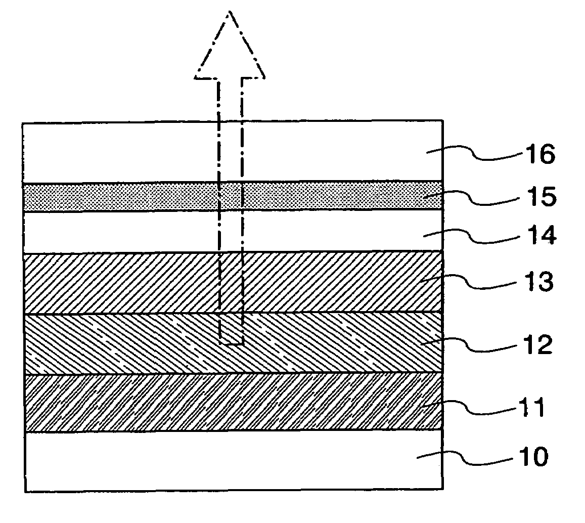
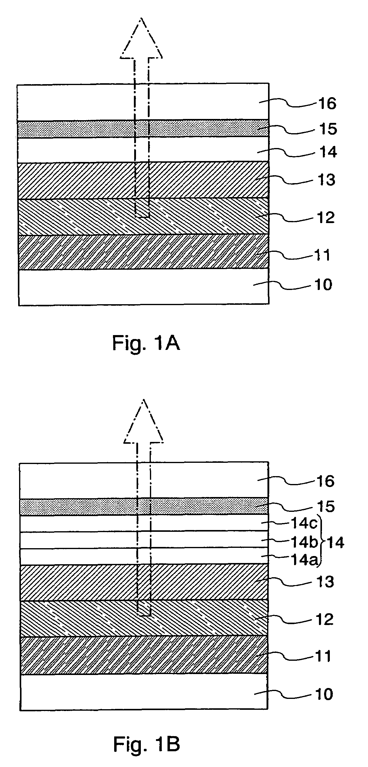
[0046]A structure of a light-emitting element according to this embodiment is explained with reference to FIG. 1A. FIG. 1A illustrates a schematic cross-sectional view of the light-emitting element according to this embodiment. The light-emitting element according to this embodiment comprises a pixel electrode 11, an electroluminescent layer 12, a transparent electrode 13, a passivation film 14, a stress relieving layer 15, and a low refractive index layer 16 as illustrated in FIG. 1A. The light-emitting element is generally provided over a substrate 10. The light-emitting element according to this embodiment is capable of emitting light to the top (so-called top emission), which comprises the passivation film 14 formed over the transparent electrode 13, the stress relieving layer 15 formed over the passivation film 14, and the low refractive index layer 16 formed over the stress relieving layer 15. The present invention can be applied to a top emission light-emitting element and a ...

embodiment 2

[0074]A structure of a light-emitting element according to this embodiment is explained with reference to FIG 1B. FIG. 1B is a schematic cross-sectional view of the light-emitting element according to this embodiment. The characteristic feature of the present invention relating to this embodiment is a passivation film 14 having a lamination layer structure. The structure illustrated in FIG 1B has a three-layer structure formed by stacking sequentially a silicon nitride film 14a, a silicon oxide film 14b, and a silicon nitride film 14c. The second layer, SiO2 film, combines a function as a passivation film and a function of preventing peeling or cracking of a SiN film (function as a stress relieving film). By forming the passivation film to have a three-layer structure, a barrier property of the passivation film is improved and penetration of impurities such as moisture or oxygen into a transparent electrode 13 or an electroluminescent layer 12 can be effectively prevented.

[0075]A st...

embodiment 3

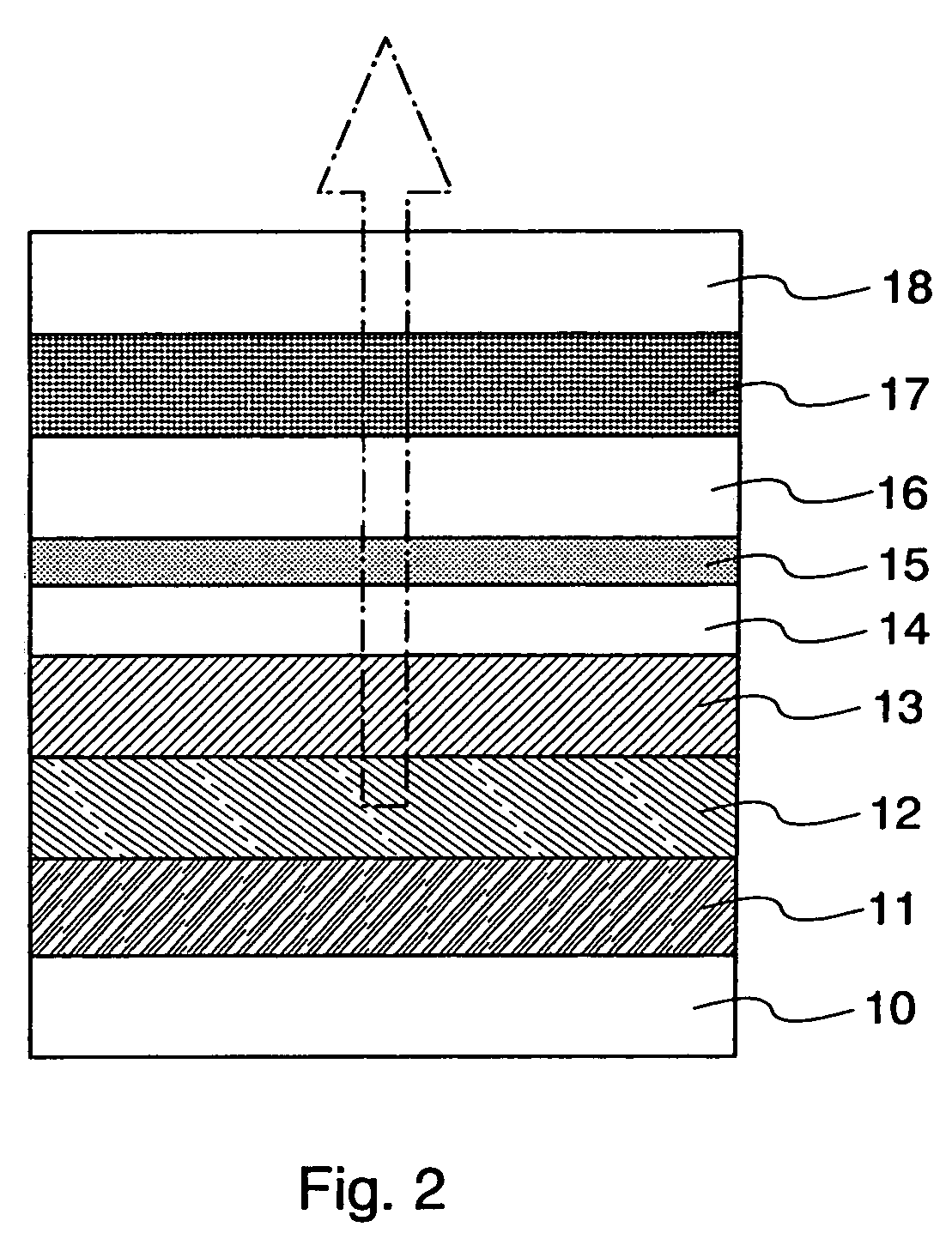
[0079]A structure of a light-emitting element according to this embodiment is explained with reference to FIG. 2. FIG. 2 is a schematic cross-sectional view of the light-emitting element according to this embodiment. The characteristic feature of the present invention relating to this embodiment is that space between a low refractive index layer 16 and an opposite substrate 18 is filled with a filling layer 17. The filling layer 17 has preferably a refractive index that is almost the same as those of a low refractive index layer 16 and an opposite substrate 18 or that is intermediate between those of the low refractive index layer 16 and the opposite substrate 18. In the case that the low refractive index layer 16 is made from LiF (n=1.30 to 1.39) and the opposite substrate 18 is formed by a glass substrate (n=1.5), a material having a refractive index of approximately 1.2 to 1.6 is preferably used as the filling layer 17. For instance, Fluorinert that is inert liquid containing flu...


PUM


Abstract

There has been a problem that difference in refractive index between an opposite substrate or a moisture barrier layer (passivation film) such as SiN provided thereover, and air is maintained large, and light extraction efficiency is low. Further, there has been a problem that peeling or cracking due to the moisture barrier layer is easily generated, which leads to deteriorate the reliability and lifetime of a light-emitting element. According to the present invention, a light-emitting element comprises a pixel electrode, an electroluminescent layer, a transparent electrode, a passivation film, a stress relieving layer, and a low refractive index layer, all of which are stacked sequentially. The stress relieving layer serves to prevent peeling of the passivation film. The low refractive index layer serves to reduce reflectivity of light generated in the electroluminescent layer in emitting to air. Therefore, a light-emitting element with high reliability and long lifetime and a display device using the light-emitting element can be provided.

Description

BACKGROUND OF THE INVENTION[0001]1. Field of the Invention[0002]The present invention relates to a light-emitting element as typified by an organic EL element and a display device having the light-emitting element.[0003]2. Related Art[0004]In recent years, a display device having a light-emitting element as typified by an organic EL (Electro Luminescence) element has been developed and expected to be widely used with taking advantages of a high quality image, a wide viewing angle, and a slim and lightweight shape due to that the display device is a self-luminous type. The “EL element” refers to a light-emitting element that uses a principle that an electroluminescent layer emits light that is interposed between a pair of electrodes by applying current to an anode and a cathode. As the light-emitting element, for example, a so-called top emission light-emitting element having a transparent electrode at a side of an opposite substrate to emit light to the side of the opposite substrat...

Claims


Application Information

Patent Timeline
Patent Type & Authority Patents(United States)
IPC IPC(8): H01L27/15H01L27/32H01L29/06H01L51/52H05B33/12
CPCG09G3/3291H01L27/3246H01L27/3272H01L51/5275H01L51/5262H01L51/5203H01L51/5012H01L27/322H01L51/5237G09G2300/0842G09G2310/0251G09G2320/043H01L51/5284H01L2251/5315H10K59/126H10K59/122H10K50/85H10K50/8426H10K50/865H10K2102/3026H10K50/844G02F1/136222H10K50/11H10K50/81H10K50/84H10K50/805H10K50/828H10K50/858H10K50/8428H10K59/35H10K59/38H10K2102/00H10K2102/311H10K2102/3031
Inventor IKEDA, HISAOOHARA, HIROKIHOSOBA, MAKOTOSAKATA, JUNICHIROITO, SHUNICHI
Owner SEMICON ENERGY LAB CO LTD
Why Eureka
Try Eureka