Gas detection method and gas detection device

A gas detection and gas technology, applied in the field of low-cost infrared gas detection, can solve the problems of slow measurement cycle, no absolute suppression technology, etc., and achieve an easy-to-achieve effect

Active Publication Date: 2007-10-31
AXETRIS AG
View PDF1 Cites 13 Cited by
  • Summary
  • Abstract
  • Description
  • Claims
  • Application Information

AI Technical Summary

Benefits of technology

This technology allows for accurate measurements on both high power (HW) light emitting diodes (LEDs), such as those used in industrial applications like machining or welding processes, without requiring any extra equipment. It also ensures consistently reliable results even when there are changes over time due to factors like ambient temperatures or agitation conditions affecting the emission characteristics of LED lights.

Problems solved by technology

Technologies described involve detectors used in industrial processes like manufacture, quality control, monitoring, and inspections. However, these technics have limitations because it requires specific parts inside the process equipment to operate correctly without causing defective products during production. These technical problem addressed by the present patents relates to improving the accuracy and resolution of gas sensory measurements while reducing variations in detected signals attributed to etialone friction patterns.

Method used


Image

  • Gas detection method and gas detection device
  • Gas detection method and gas detection device
  • Gas detection method and gas detection device

Examples


Embodiment Construction

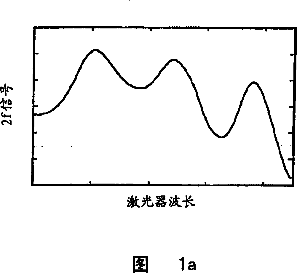
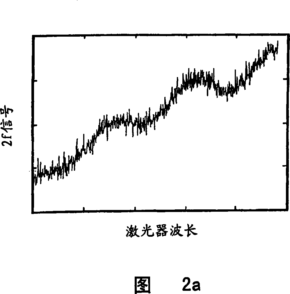
[0048] As mentioned above, the present invention is based on the measurement technique described in the above two patent application documents.

[0049] The tunable laser 1 is focused on the gas absorption peak of the measured gas by appropriate laser DC driving current. The temperature of the laser is usually kept at a constant value to avoid wavelength drift of the laser light caused by temperature changes of the laser. An AC current of frequency f is superimposed on the DC laser current so that the laser beam wavelength oscillates at frequency f around the gas absorption peak.

[0050]The laser light is emitted through the gas volume 4 containing the gas to be measured and is then incident on a photodiode as a detection device. The AC modulation of the laser drive current is connected to the intensity oscillations of the light output of the laser, which occur at the modulation frequency f. When a target gas is present in the gas absorption path, a portion of the laser lig...


PUM


Abstract

The invention proposes a method for etalon suppression in a gas detection device by determining an etalon fringe period during a calibration step without gas in dependency of the DC drive current. A measuring signal which is a function of the gas absorption and substantially independent of an intensity modulation of an initial light signal at an initial frequency (f) is generated by determining a first pre-measuring signal when the laser source is operated at the center of the gas absorption peak, a second pre-measuring signal when the laser source is operated with a DC drive current below the gas absorption peak of the gas to be detected, and a third pre-measuring signal when the laser source is operated with a DC drive current above said gas absorption peak, with a difference between said DC drive currents which corresponds to the etalon fringe period determined in a calibration step before. The final measuring signal is determined as the difference between the first pre-measuring signal and the arithmetic mean of the second pre-measuring signal and the third pre-measuring signal. This etalon fringe suppression allows to implement a substantial simplification of a reference channel in a gas detector, which does not require separate lock-in channels which analyse the detector signal either on the modulation frequency (f), or on twice the modulation frequency (2f).

Description


Claims


Application Information

Patent Timeline
Owner AXETRIS AG
Why Eureka
Try Eureka