Imaging optics with adjustable optical power and method of adjusting an optical power of an optics

an optics and optical power technology, applied in optics, microscopes, lenses, etc., can solve the problems of disturbing effect, unreasonably complex required mechanics, and complex mechanics, and achieve the effect of simplifying the zoom system

Inactive Publication Date: 2008-08-12
OBREBSKI ANDREAS
View PDF34 Cites 16 Cited by
  • Summary
  • Abstract
  • Description
  • Claims
  • Application Information

AI Technical Summary

Benefits of technology

[0015]It is an object of the present invention to provide a zoomable imaging optics, wherein the required optical imaging quality is appropriately achieved by use of a lens of variable optical power.
[0049]In particular, it is then also possible to provide simplified zoom systems in the partial stereo optics in that, when a magnification provided by the zoom systems is changed, the intensity of the round lens action can be changed as well.

Problems solved by technology

In order to correctly displace these two lens assemblies relative to one another and relative to the fixedly positioned lens assembly, quite complex mechanics are required.
However, if the optical power of the lens of variable optical power is varied to change the magnification, imaging aberrations occur which have a disturbing effect.
If, in such a stereo-microscopy system, a working distance between the object plane and the objective assemblies is to be changed, the angle between the two principal axes must be changed accordingly, which renders the required mechanics unreasonably complex under practical aspects.

Method used


Image

  • Imaging optics with adjustable optical power and method of adjusting an optical power of an optics
  • Imaging optics with adjustable optical power and method of adjusting an optical power of an optics
  • Imaging optics with adjustable optical power and method of adjusting an optical power of an optics

Examples


Embodiment Construction

[0072]In the exemplary embodiments described below, components that are alike in function and structure are designated as far as possible by alike reference numerals. Therefore, to understand the features of the individual components of a specific embodiment, the descriptions of other embodiments and of the summary of the invention should be referred to.

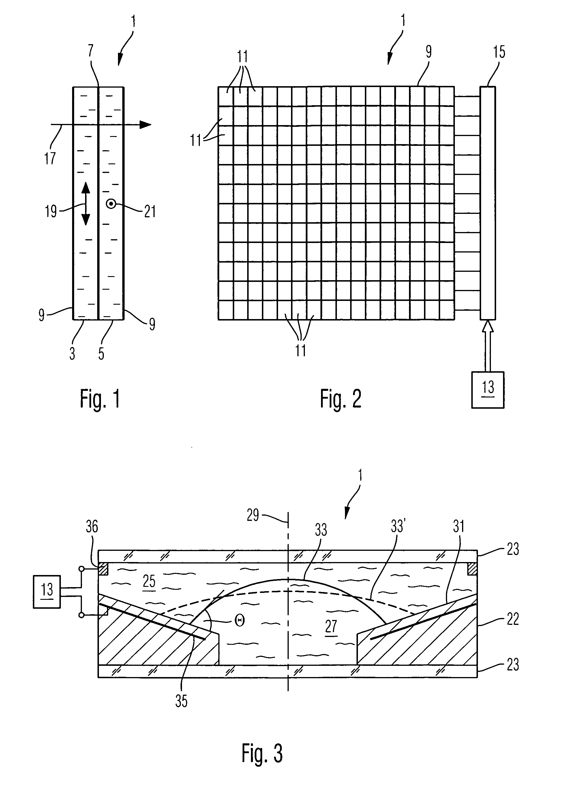
[0073]Embodiments of the imaging optics according to the invention will now be described in further detail which include lenses of variable optical power. First of all, an embodiment of such a lens of variable optical power will be described below with reference to FIGS. 1 and 2. Such lenses are known, for example, from U.S. Pat. No. 4,795,248, U.S. Pat. No. 6,317,190 B1, U.S. Pat. No. 5,617,109, U.S. Pat. No. 4,909,626, U.S. Pat. No. 4,781,440, U.S. Pat. No. 4,190,330, U.S. Pat. No. 4,572,616 and U.S. Pat. No. 5,815,233, the full disclosures of which are incorporated herein by reference.

[0074]FIG. 1 shows a cross-section through a l...


PUM

PropertyMeasurementUnit
focal lengthaaaaaaaaaa
working distanceaaaaaaaaaa

Abstract

The invention relates to optics comprising adjustable optical elements and, if desired, lenses of fixed focal lens. By use of an appropriate controller for the adjustable optical elements, characteristics of the optics can be advantageously varied. For this purpose, systems are provided which are suitable for use as surgical stereo-microscope, objective, ocular or zoom. A zoomable imaging optics comprises lenses and of variable optical power, which are oppositely controlled by means of a controller to change an imaging ratio, so that the optical power of the one lens is increased and the optical power of the other lens is decreased. Moreover, the imaging optics may comprise still further assemblies of fixed optical power.

Description

[0001]This application is a continuation application of PCT Application Number PCT / EP2004 / 012042, filed Oct. 25, 2004, which claims priority from German Patent Application No. 103 49 293.3 filed on Oct. 23, 2003 and German Patent Application No. 10 2004 026 580.1 filed on Jun. 1, 2004.BACKGROUND OF INVENTION[0002]1. Field of the Invention[0003]The invention relates to imaging optics with adjustable optical power. The imaging optics is an optics of very general nature for use, for example, in a camera, telescope, a microscope or other optics. Furthermore, the invention relates to a method of adjusting an optical power in particular of a zoomable imaging optics.[0004]Furthermore, the invention relates to a stereo-microscopy system for generating a magnified stereoscopic image of an object, as well as to a corresponding stereo-microscopy method.[0005]A zoomable imaging optics is an imaging optics, the imaging ratio or magnification of which is variable.[0006]2. Brief Description of Rel...

Claims


Application Information

Patent Timeline
Patent Type & Authority Patents(United States)
IPC IPC(8): G02B1/06G02B21/22G02B3/12G02F1/13G02B3/14G02B15/00G02B21/02
CPCG02B3/14G02B15/00G02B26/005G02B21/22G02B21/025
Inventor OBREBSKI, ANDREASSTRAHLE, FRITZ
Owner OBREBSKI ANDREAS
Why Eureka
Try Eureka