Projection device

A technology of projection device and generating device, applied in the field of temperature control system, can solve the problems of lack of

Inactive Publication Date: 2007-10-31
DELTA ELECTRONICS INC
View PDF0 Cites 6 Cited by
  • Summary
  • Abstract
  • Description
  • Claims
  • Application Information

AI Technical Summary

Problems solved by technology

[0005] The cooling technologies for projection systems on the market, no matter water cooling or air cooling, have proposed many solutions, but for the technology of heating the system to normal operating temperature under extremely low

Method used


Image

  • Projection device
  • Projection device
  • Projection device

Examples


Embodiment Construction

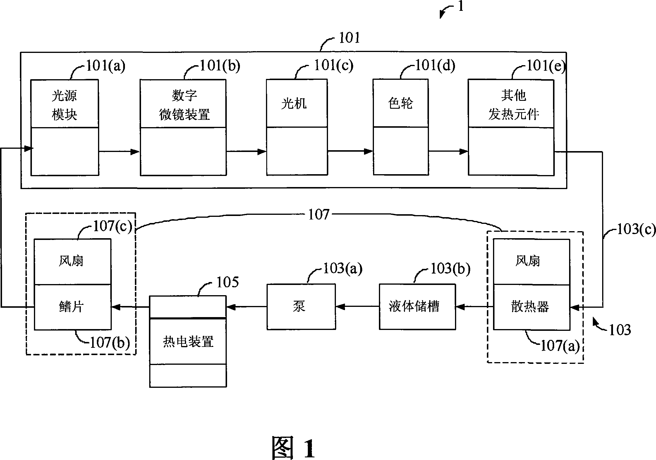
[0055]The preferred embodiment of the present invention is shown in Figure 1, which is a temperature control system. This temperature control system is used in the projection device 1. The projection device 1 includes a plurality of heating elements 101. The ambient temperature of these heating elements 101 can be adjusted through the temperature control system of the present invention, so that the projection device can operate at the expected proper working temperature. operate. These heating elements 101 may include a light source module 101(a), a digital micromirror device (DMD) 101(b), an optical engine (optical engine) 101(c), a color wheel (color wheel) 101(d) and / or For other heating elements 101(e), etc., the positions of the elements in the heating element 101 can be appropriately set according to their temperature requirements; in addition, when the light source module 101(a) is a light emitting diode (light emitting diode, LED) module, the heating element 101 The c...


PUM


Abstract

This invention relates to one projection device with temperature control system, which comprises at least one light element, wherein the temperature control system has liquid tube system, thermal energy generation device and deliver device; the tube system is set along at least one light element; the energy device can generate positive or negative energy in environment and then thermal energy through aid device along liquid tube system without outer impact; the sustain projection device is set in one needed work temperature to keep temperature balance.

Description

technical field [0001] The invention relates to a temperature control system for a projection device, in particular to a technology capable of generating or dissipating heat energy correspondingly according to different ambient temperatures, and maintaining a proper working temperature of the projection device. Background technique [0002] For projection systems, especially large-scale, high-load, and high-heat projection systems, the cooling system is an important part of maintaining the operation of the internal components of the projector at a certain temperature and prolonging the service life of the internal components in the internal component configuration. When the projection system is in operation, the internal components can be divided into low-temperature components and high-temperature components. Through proper cooling channel design, the cooling fluid can first pass through the low-temperature components, and then flow through the high-temperature components fo...

Claims


Application Information

Patent Timeline
IPC IPC(8): G03B21/16G05D23/00H05K7/20
Inventor 林嘉瑞张修铭张国卿林慧芝曹裕后
Owner DELTA ELECTRONICS INC
Why Eureka
Try Eureka