Heat sinking control system and method

A technology of control system and control method, applied in the field of control, to achieve the effect of solving measurement lag

Inactive Publication Date: 2007-10-31
INVENTEC CORP
View PDF0 Cites 16 Cited by
  • Summary
  • Abstract
  • Description
  • Claims
  • Application Information

AI Technical Summary

Problems solved by technology

The usual practice is to associate each temperature sensor with the cooling fan one by one, but there is also a lack of this. For example, the temperature sensor that measures the CPU temperature only corresponds to the cooling fan that controls the nearest CPU. When it is extremely difficult to lower the temperature of the CPU, the other nearby fans will not increase the speed to ensure effective cooling of the CPU

Method used


Image

  • Heat sinking control system and method
  • Heat sinking control system and method
  • Heat sinking control system and method

Examples


Embodiment

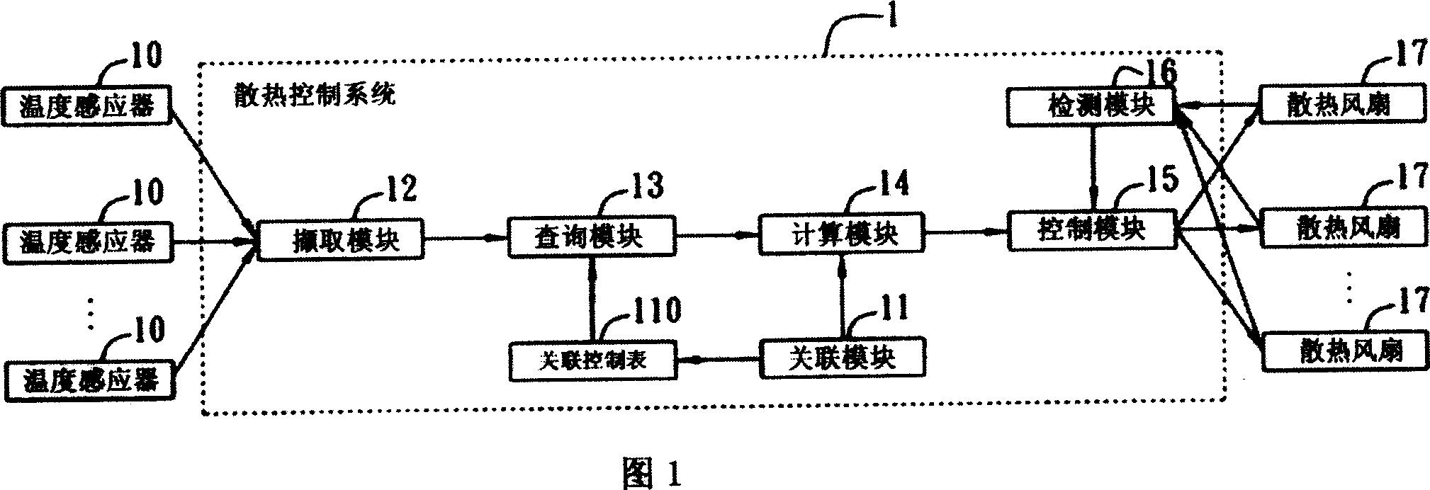
[0022] FIG. 1 is a schematic diagram of the detailed architecture of the heat dissipation control system of the present invention. As shown in the figure, the heat dissipation control system 1 of the present invention controls the operating state of at least one heat dissipation device such as a heat dissipation fan 17 according to the temperature value measured by at least one temperature sensor 10. In this embodiment, the heat dissipation fan 17 is set Cooling fans in server chassis. The heat dissipation control system includes an association module 11 , an acquisition module 12 , a query module 13 , a calculation module 14 , a control module 15 and a detection module 16 . In addition to the cooling fan, the heat dissipation device is also a liquid cooling system. The heat dissipation control system of the present invention can control the pump body of the liquid cooling system to process the flow rate of the cooling liquid. In the following embodiments, the cooling fan is u...


PUM


Abstract

This invention discloses one dissipation control system and method, which comprises connection module, inquire module, inquire module, computation module and control module, wherein the method comprises the following steps: generating relative control list; computing each temperature change values; getting relative volume temperature value and change value; getting change value and its control value; computing each dissipation device control value; accordingly computing each device control device to output one control signal to relative dissipation device to control each device operation status.

Description

technical field [0001] The present invention relates to a control technology, in particular to a heat dissipation control system and method for controlling the operating state of heat dissipation equipment such as heat dissipation fans by combining temperature information, temperature change information, and information related to temperature sensors and heat dissipation fans. Background technique [0002] With the high integration of large-scale integrated circuits in electronic devices such as server systems, the operating frequencies of central processing units (Central Processing Unit, CPU), hard disks and other components are getting higher and higher, and the heat generated by the entire system is also increasing. If the heat in the server chassis cannot be dissipated in time, the accumulated heat will cause various devices or components in the system to fail to work normally due to continuous heating, and more seriously may cause devices or components to malfunction or...

Claims


Application Information

Patent Timeline
Patent Type & Authority Applications(China)
IPC IPC(8): G05B19/02
Inventor 邹小兵陈志丰
Owner INVENTEC CORP
Why Eureka
Try Eureka