Deep foundation pits rampway structure

A technology for deep foundation pits and ramps, which is applied in the fields of infrastructure engineering, building construction, and on-site preparation of building components, can solve problems such as increasing the difficulty of excavating foundation pits, increasing construction costs, and prolonging construction period, and achieves shortening The effect of construction period, improving efficiency and improving the scope of application

Inactive Publication Date: 2007-11-07
天津一建建筑工程有限公司
View PDF0 Cites 13 Cited by
  • Summary
  • Abstract
  • Description
  • Claims
  • Application Information

AI Technical Summary

Problems solved by technology

In the actual construction site, the required ramp length is often not reached in the deep foundation pit. At this time, it is necessary to use more advanced mechanical equipment or a combination of manual and mechanical equipment for excavation and transportation, thus increasing the foundation. The difficulty of excavating the pit prolongs the construction period and also increases the construction cost

Method used


Image

  • Deep foundation pits rampway structure
  • Deep foundation pits rampway structure
  • Deep foundation pits rampway structure

Examples


Embodiment 1

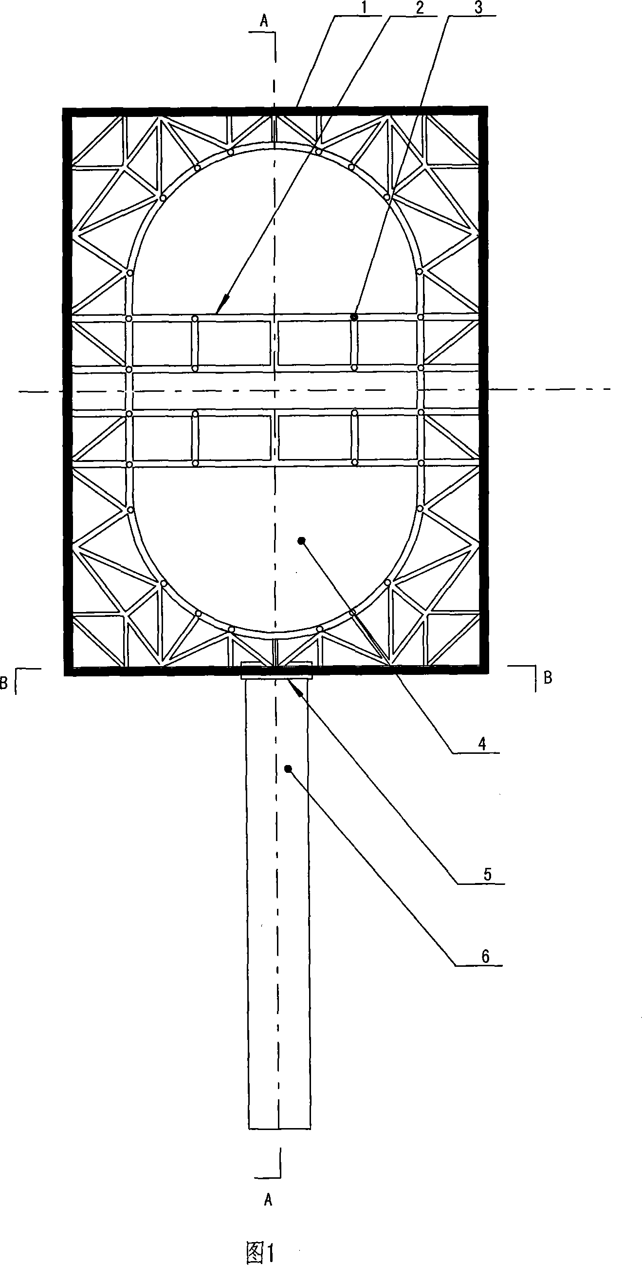
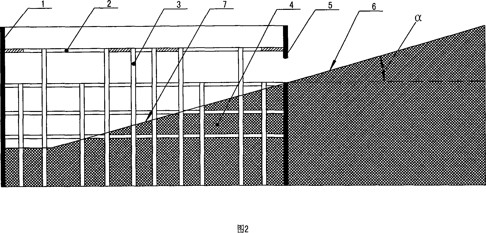
[0024] As shown in Figure 1, Figure 2 and Figure 4, the ramp structure of the deep foundation pit is composed of a deep foundation pit 4, an enclosure structure 1, a horizontal support frame 2 and a vertical support frame 3, and a vertical support structure is built around the deep foundation pit Enclosure structure, the enclosure structure includes the peripheral underground diaphragm wall (not shown in the figure) and the temporary partition enclosure (not shown in the figure) inside the deep foundation pit, and the temporary partition enclosure inside the deep foundation pit adopts Drilling and grouting piles combined with a single row of rotary grouting piles for water-stop curtains; 3 to 6 horizontal support frames can be fixed vertically at the inner end of the enclosure structure. The horizontal support frames in this embodiment have four horizontal support frames. From top to bottom are the first horizontal support frame, the second horizontal support frame, the third h...

Embodiment 2

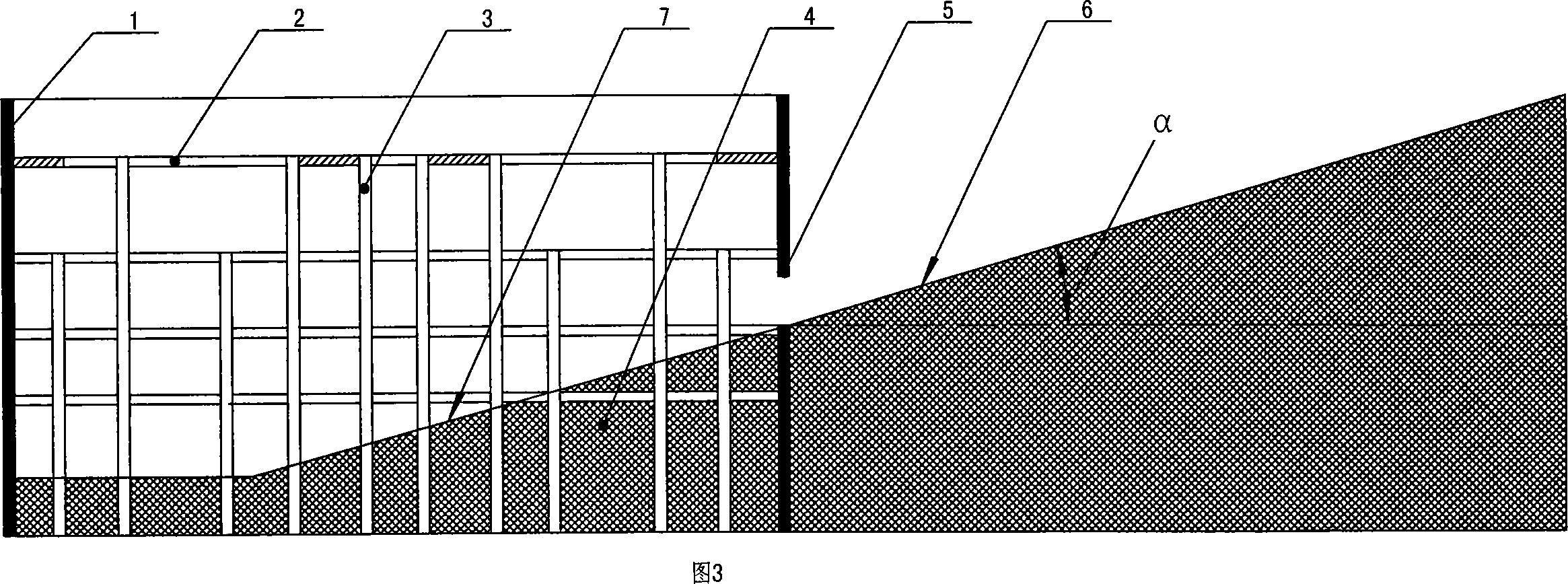
[0026] As shown in FIG. 3 , in this embodiment, the door opening of the ramp is set on the enclosure structure between the second horizontal support frame and the third horizontal support frame, and other structures are completely the same as those in Embodiment 1. Compared with Embodiment 1 in this way, the ramp doorway is located at the third horizontal support frame. Since the position of the ramp doorway is lower than that of the ramp doorway in Embodiment 1, the ramp outside the pit The length is longer than the ramp outside the pit in embodiment 1, and the length of the ramp in the pit is shorter, this mode is suitable for the situation that there is plenty of space outside the deep foundation pit and the length of the deep foundation pit is limited.

Embodiment 3

[0028] As shown in FIG. 5 , in this embodiment, the ramp 6 outside the pit is a curved ramp structure, and other structures are exactly the same as those in Embodiment 1. This method has a certain amount of space in front of and on both sides of the ramp door opening, but each direction cannot fully meet the needs of the ramp length, so the form of this curved ramp can be used to solve the problem.


PUM


Abstract

The present invention relates to building engineering technology, and is especially one kind of deep foundation pit ramp structure. The deep foundation pit ramp structure consists of a deep foundation pit, a vertical enclosing structure around the deep foundation pit, a horizontal holding frame inside the enclosing structure, and a vertical holding frame fixed below the horizontal holding frame. Technologically, the present invention features that the enclosing structure is provided with one ramp door opening connecting one outer ramp outside the enclosing structure and one inner ramp inside the deep foundation pit. By means of combining the outer ramp and the inner ramp, the present invention makes it possible to construct long ramp in limited site. The deep foundation pit ramp structure facilitates the deep foundation pit construction.

Description

technical field [0001] The invention belongs to construction engineering devices, in particular to a deep foundation pit ramp structure. Background technique [0002] The excavation of the foundation pit is an important construction link in the construction process, and it plays an important role in the construction cost and construction period. At present, in the excavation process of the foundation pit, a ramp in the pit for excavators, shovels and transport vehicles to travel is built on the side of the foundation pit along with the downward excavation of the foundation pit. The slope of the slope in the pit should not be too steep, generally less than 20 degrees. The excavator drives along the slope in the pit to the foundation pit to continue excavating the earth. The excavated earth is loaded into the transport vehicle and It is transported out from the ramp in the pit by the transport vehicle. This kind of in-pit ramp extending from the side of the foundation pit in...

Claims


Application Information

Patent Timeline
Patent Type & Authority Applications(China)
IPC IPC(8): E02D17/02E04G27/00
Inventor 李建军
Owner 天津一建建筑工程有限公司
Why Eureka
Try Eureka