Vertical shaft wind power machine wind wheel

A wind power and machine wind technology, applied in the field of wind energy utilization devices, can solve the problems of low wind energy utilization efficiency, poor wind energy utilization rate, and low starting wind speed, and achieve high wind energy utilization efficiency, low starting wind speed requirements, and flexible opening and closing Effect

Inactive Publication Date: 2007-11-07
戴玉毅
View PDF6 Cites 6 Cited by
  • Summary
  • Abstract
  • Description
  • Claims
  • Application Information

AI Technical Summary

Problems solved by technology

[0004] The blades of the wind wheel of the resistance type vertical axis wind turbine are cross-blocked on the passage of the air flow. When the air flow is used to blow to the blade, the large pressure difference between the front and back of the blade forms a thrust to push the wind wheel to rotate, as disclosed in the disclosed invention (CN85108096A, CN1450263A , CN1474050A, CN2505613Y) wind rotor blades are resistance type, the advantage of this type of wind rotor is that the requirement for starting wind speed is relatively low, and the disadvantage is that the utilization efficiency of wind energy is relatively low
[0005] Recently, there is also a kind of resistance and lift composite wind power device, such as the disclosed invention (CN200510044144.8), which is to use the hollow cavity formed by the airfoil blades made of thin plates to block the wind and generate thrust. Pushing the wind wheel to rotate, its wind energy utilization rate is still not good

Method used


Image

  • Vertical shaft wind power machine wind wheel
  • Vertical shaft wind power machine wind wheel
  • Vertical shaft wind power machine wind wheel

Examples


Embodiment Construction

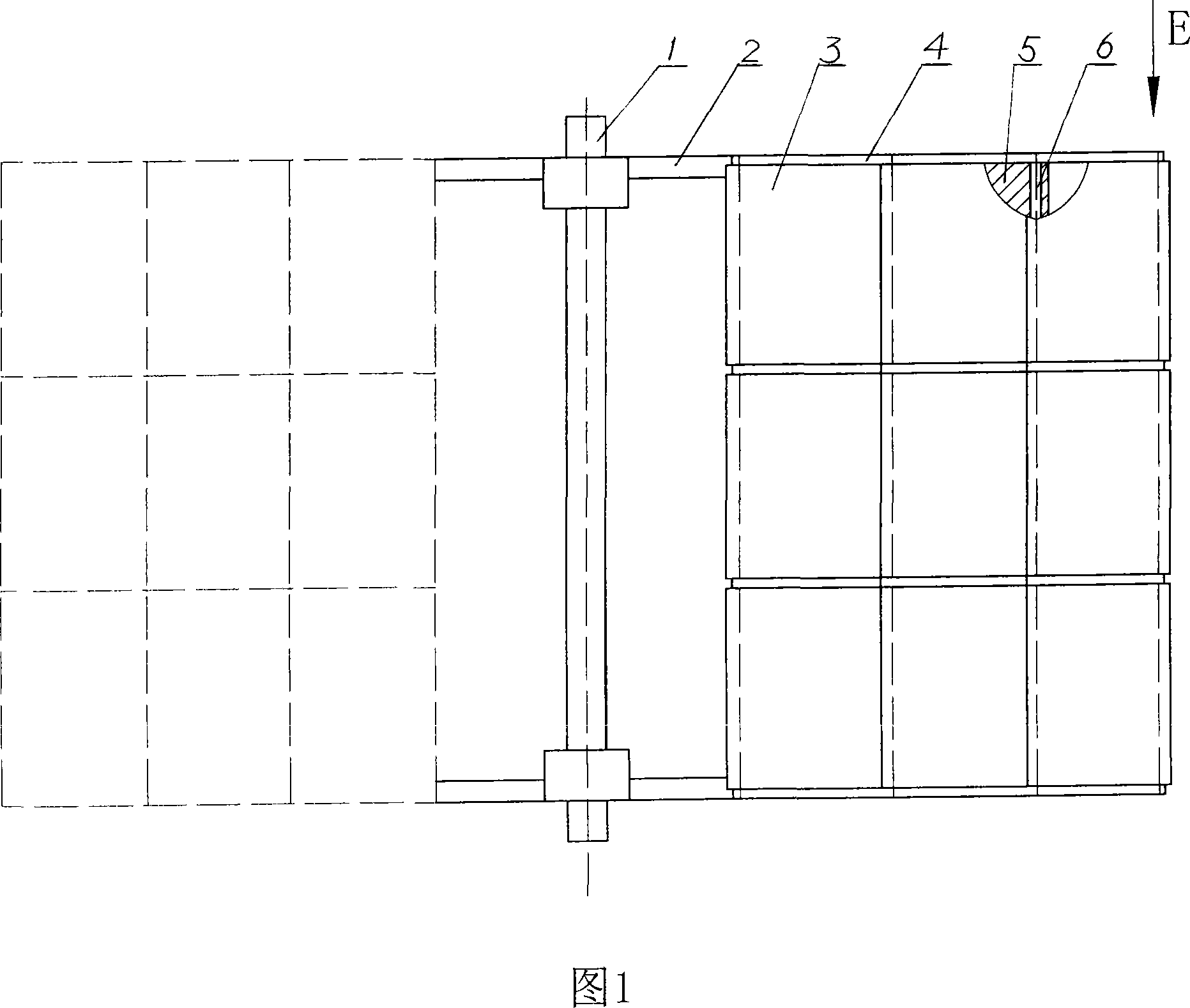
[0022] Embodiments of the present invention will be further described below in conjunction with the accompanying drawings.

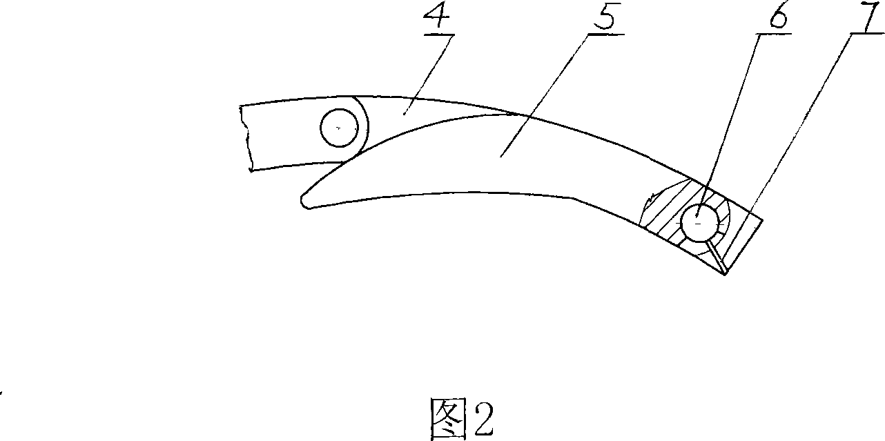
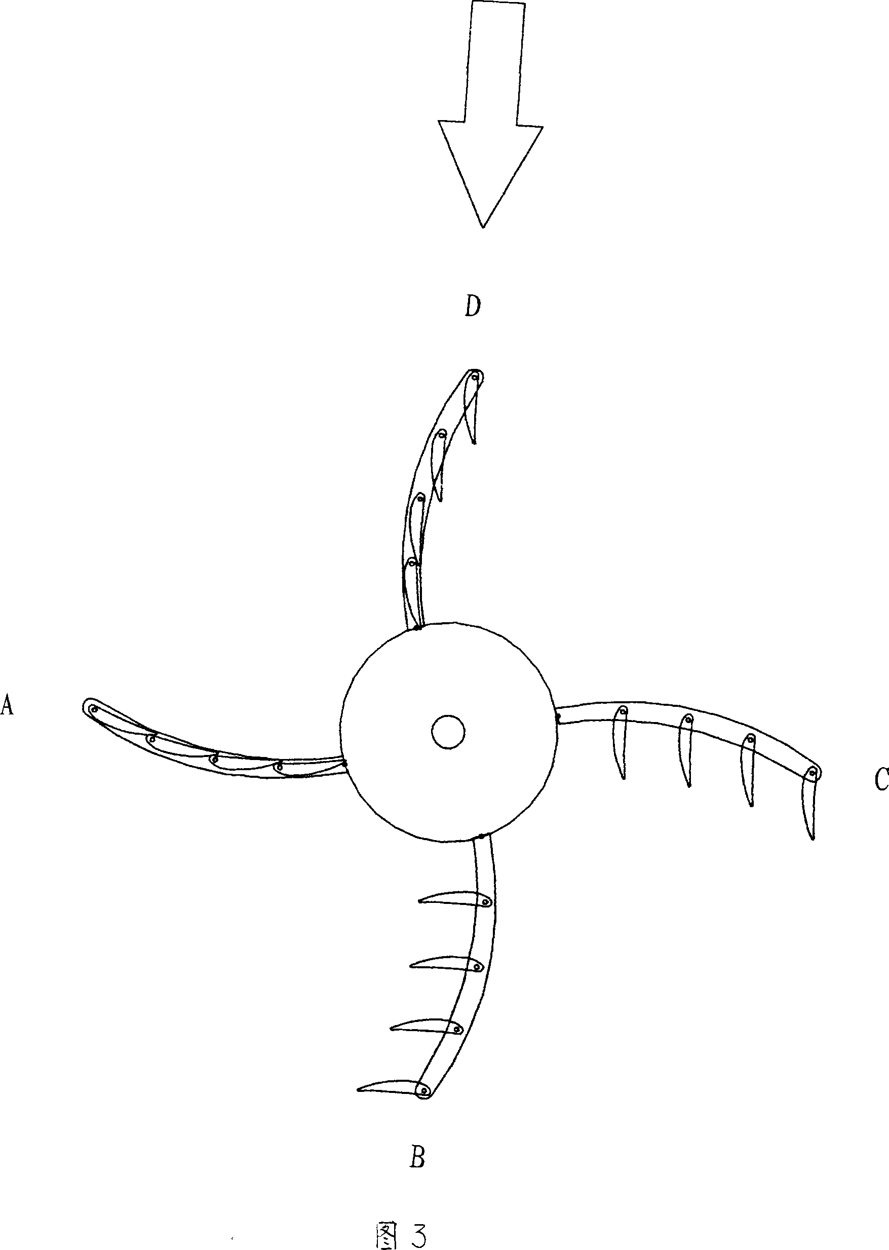
[0023] The wind rotor of the vertical axis wind turbine is mainly composed of a central shaft 1, a connecting rod 2 and 4 arc-shaped curved blades 3 uniformly arranged around the central shaft along the circumferential direction of the wind rotor. The size, curvature and arc direction of each arc-shaped curved blade are consistent, and the convex surfaces thereof all face the rotation direction of the wind wheel. The blades are provided with 4 bow-shaped lateral supports 4 and 4 vertical shafts 6 parallel to the central axis, a rectangular grid is formed between adjacent lateral supports and vertical shafts, and each grid part is provided with a movable blade body 5, The wind blade body is similar to the shape of an airplane wing, and is located on the concave side of the blade. Its leading edge is in rotational fit with the vertical shaft, and the slidi...


PUM


Abstract

A vertical shaft wind wheel relates to the device to use the wind energy. It is made up of the central axis, the connecting pole and more than 3 vanes. The vane is the arc curved vane which is set with the arc cross support and the vertical axis in the arc curved; the rectangle grid forms between the cross support and the vertical axis. The grid part is set with the active wind vane and the limiting part to control the wind vane rotating angle. The wind vane section is the airfoil shape which the front part matches with the vertical axis. The invention is installed on the vertical axis wind fan which the central axis and the arc vane are vertical to the ground. Under the level wind force, the wind vane on vane is forced by the thrust F1, the oblique force F2 and the lift force F3 to generate the moment M1, M2 and M3 to make the wind wheel rotate in a same direction; it would rotate continuously until the wind force stops. The invention can transform the wind energy into the electric energy or mechanism energy by many modes; also it has low request for the starting wind speed and high wind energy using efficiency.

Description

technical field [0001] The invention relates to a wind wheel of a vertical axis wind power machine, and belongs to the technical field of wind energy utilization devices. Background technique [0002] Wind turbines can convert wind energy into mechanical energy or electrical energy, and have broad application prospects. As the core component of wind turbines, wind rotors have an important impact on the energy conversion efficiency. The wind rotors of existing vertical axis wind turbines are divided into two types according to the way the wind pushes the wind rotors: lift type and drag type. [0003] The blades of the lift-type vertical axis wind turbine are similar to the wings of an airplane. When the air flow passes by, the lift produced by the blades as wings pushes the wind wheel to rotate, such as the disclosed invention (CN85201691). It is a lift type. The advantage of this type of wind rotor is that it is simple in structure. The disadvantage is that it requires a hi...

Claims


Application Information

Patent Timeline
Patent Type & Authority Applications(China)
IPC IPC(8): F03D3/06
CPCY02E10/74
Inventor 戴玉毅
Owner 戴玉毅
Why Eureka
Try Eureka