Heat-gathering pot support

A heat collecting pot and hot pot technology, applied in the field of pot support, can solve the problem of high heat loss and other problems

Inactive Publication Date: 2007-11-07
姜亦迎
View PDF0 Cites 0 Cited by
  • Summary
  • Abstract
  • Description
  • Claims
  • Application Information

AI Technical Summary

Problems solved by technology

[0003] The technical problem to be solved by the present invention is to provide a heat collectin

Method used


Image

  • Heat-gathering pot support
  • Heat-gathering pot support

Examples


Embodiment Construction

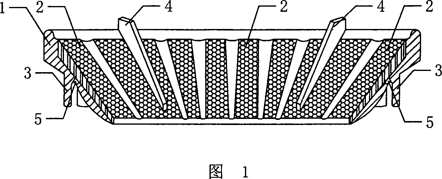
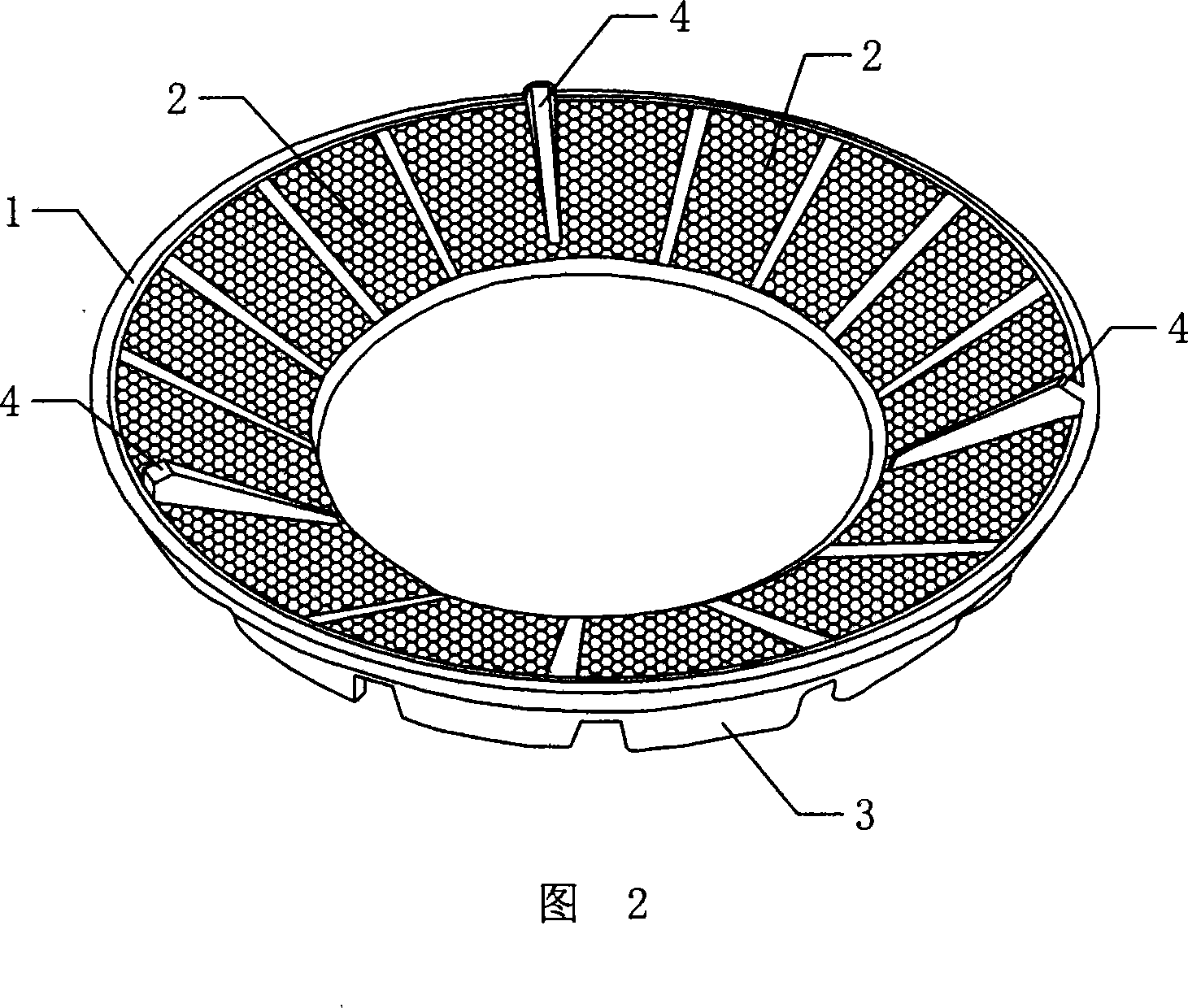
[0011] As shown in Figures 1 and 2, the heat-collecting pot bracket includes a bracket body 1 with an opening corresponding to the furnace head in the middle. The bracket body 1 is ring-shaped, and the outer circumference of the bracket body 1 is fixed with a stable The ring-shaped support foot 3 of the bracket body 1, the ring-shaped support foot 3 is stable and firm to the bracket body 1, and now there is a ring-shaped protrusion on the water tray of the gas stove, and the ring-shaped support foot 3 is installed The bracket body 1 is fixed on the annular protrusion; the bracket body 1 is fixed with three pot bottom supporting claws 4 for supporting the bottom of the pot, and a number of burning flames are installed on the inner side of the bracket body 1 The bottom of the refractory heating plate 2 is covered with through holes, and the surface of the heating plate 2 is provided with concavities and convexities that can reflect the combustion flame and collect it on the bottom o...


PUM


Abstract

The invention discloses a kind of collector heat pan bearer it concludes the bearer body setting a open hole corresponding the head of oven in the center and the on the bearer body said above sets up a pan floor fasten flaw used to support the pan floor and the internal of bearer body sets up many fire-resisting reverse hot plate which can assemble the burning flame to the pan floor. By mirroring of the fire-resisting reverse hot plate to the igniting flame the flame which is generated during the igniting can be assembled to the pan floor so it not only resolve the problem that the ordinary pan bearer losses so lots of quantity of heat when it is igniting but also improve the work environment of chicken and save the energy.

Description

Technical field [0001] The invention relates to a gas appliance, in particular to a pot holder which is placed on a gas stove to support the pot and can collect heat. Background technique [0002] As we all know, since the introduction of gas, the pot holders of household gas stoves have placed a drip tray on the burner of the gas stove, and then put a common pot holder on it, and then put the pot on it to start burning and heating. The heating method has the following disadvantages: 1. During the reburning process of the ordinary pot holder, one-third of the heat is dissipated into the air, which is the so-called heat loss; 2. The structure of the ordinary pot holder determines that there is no auxiliary device during the combustion process. The oxygen function makes the combustion incomplete and poor atomization, that is, the so-called "chemical heat" loss; 3. During the combustion process, a part of the heat is transferred to the stove shell, which is lost through heat transfe...

Claims


Application Information

Patent Timeline
IPC IPC(8): F24C15/18
Inventor 姜亦迎
Owner 姜亦迎
Why Eureka
Try Eureka