
Magnetic disc screw locking device

A locking device, a technology for magnetic disks, applied in the field of magnetic disk manufacturing, can solve the problems of inability to ensure the verticality and stable pressure of tightening screws, damage to the hard disk of the screw sliding wire, low screw installation efficiency, etc., achieving good consistency, good verticality, low cost effect

Inactive Publication Date: 2007-11-07
YITUO SCI & TECH CO LTD SHENZHEN
View PDF0 Cites 8 Cited by
  • Summary
  • Abstract
  • Description
  • Claims
  • Application Information

AI Technical Summary

Problems solved by technology

This method of operation has the following disadvantages: 1) due to the manual operation, the installation efficiency of the screws is relatively low, resulting in high manufacturing costs; The hard disk is damaged, and the consistency of assembly is relatively low

Method used


Image

  • Magnetic disc screw locking device

Examples


Embodiment Construction

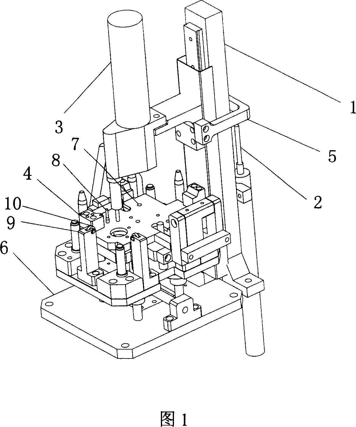
[0020] The disk screw locking device of the present invention will be further described below with reference to the accompanying drawings and embodiments.

[0021] The disk screw locking device shown in Figure 1 includes: a bracket 1, a push rod mechanism 2, a locking screw mechanism 3, a disk positioning fixture 4, and a sliding frame 5; the locking screw mechanism 3 is used for sucking and tightening screws, and disk positioning The clamp 4 is used to fix the magnetic disk; the carriage 5 is fixedly connected with the lock screw mechanism 3 and can slide up and down on the bracket 1; the ejector mechanism 2 can push up the carriage 5 and drive the lock screw mechanism 3 to slide to a predetermined position along the bracket 1 .

[0022] In order to meet the pressure requirements of disks of different specifications on the locking screws, a counterweight can be arranged on the sliding frame 5 or the locking screw mechanism 3 . The ejector mechanism 2 can be driven by a motor...


PUM


Abstract

This invention discloses a disc screw locking device including: a frame, a mandril unit, screw-locking unit, a disc localizing clamp and a sliding frame, in which, the screw-locking unit is used in extracting and screwing down screws and the disc localizing clamp is used in fixing the disc, the sliding frame is fixedly connected with the screw-locking unit sliding up and down on the frame and the sliding frame is supported above the mandril unit.

Description

technical field [0001] The invention relates to the field of disk manufacturing, in particular to an automatic locking device for disk screws. Background technique [0002] In the existing magnetic disk manufacturing process, when installing a magnetic disk, an operator generally uses an electric screwdriver to manually tighten the screws. This method of operation has the following disadvantages: 1) due to the manual operation, the installation efficiency of the screws is relatively low, resulting in high manufacturing costs; The hard disk is damaged, and the consistency of assembly is relatively low. Contents of the invention [0003] The technical problem to be solved by the invention is to provide a screw locking device capable of automatic disk screw assembly and not easy to damage the disk. [0004] The technical solution to solve the technical problem of the present invention is: a magnetic disk screw locking device, comprising: a locking screw mechanism and a magn...

Claims


Application Information

Patent Timeline
Patent Type & Authority Applications(China)
IPC IPC(8): G11B33/00B23P19/06
Inventor 李源海
Owner YITUO SCI & TECH CO LTD SHENZHEN
Learn More