Method for processing nylon zipper and zipper stopper and zipper stopper welder

A welding machine and zipper technology, applied in the field of zipper, can solve the problems of zipper not easy to lay flat, nylon material is hard, metal buckle scratches clothes, etc. The effect of efficiency

Inactive Publication Date: 2007-11-14
钟砚宝
View PDF0 Cites 8 Cited by
  • Summary
  • Abstract
  • Description
  • Claims
  • Application Information

AI Technical Summary

Problems solved by technology

[0002] Most of the known zipper stoppers are metal buckles. Because the metal buckle is bent from a metal strip, its two ends are not closed, so the two ends are easy to scratch the clothing close to it. If the zipper is installed on Pillows, the two ends of the metal buckle not closed, also prone to trapping human hair
Not only that, when the slider repeatedly hits the upper stop or the lower stop, because the two ends of the metal buckle are not closed, it is easy to make the metal buckle open, causing the slider to slip off from the tooth chain
[0003] There is also a buckle made of nylon material, which is injection-molded between the upper and lower surfaces of two zipper tapes and connects the ends of the two zipper tapes together. Its cross section is "I"-shaped. Although it solves the problem that the metal buckle is easy to scratch the clothing, because the nylon material is hard after heat curing, and the buckle is fixed between the upper and lower surfaces of the zipper tape, the zipper will not be damaged when the zipper is sewn on the clothing. It is easy to lay flat, and the buckle is also easily broken by the head of the sewing machine
[0004] At the same time, most of the zipper buckles are injection molded, that is, the molten plastic is directly injected into the upper or lower end of the zipper tape to form a closed or "I"-shaped buckle, which has low efficiency and unstable quality.

Method used


Image

  • Method for processing nylon zipper and zipper stopper and zipper stopper welder
  • Method for processing nylon zipper and zipper stopper and zipper stopper welder
  • Method for processing nylon zipper and zipper stopper and zipper stopper welder

Examples


Embodiment Construction

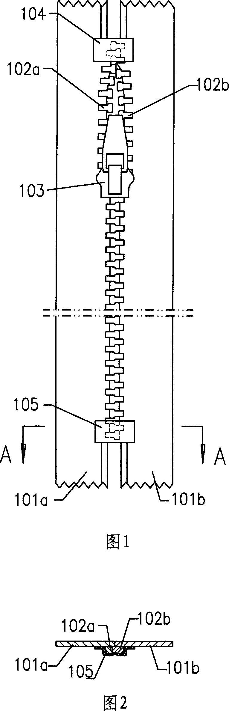
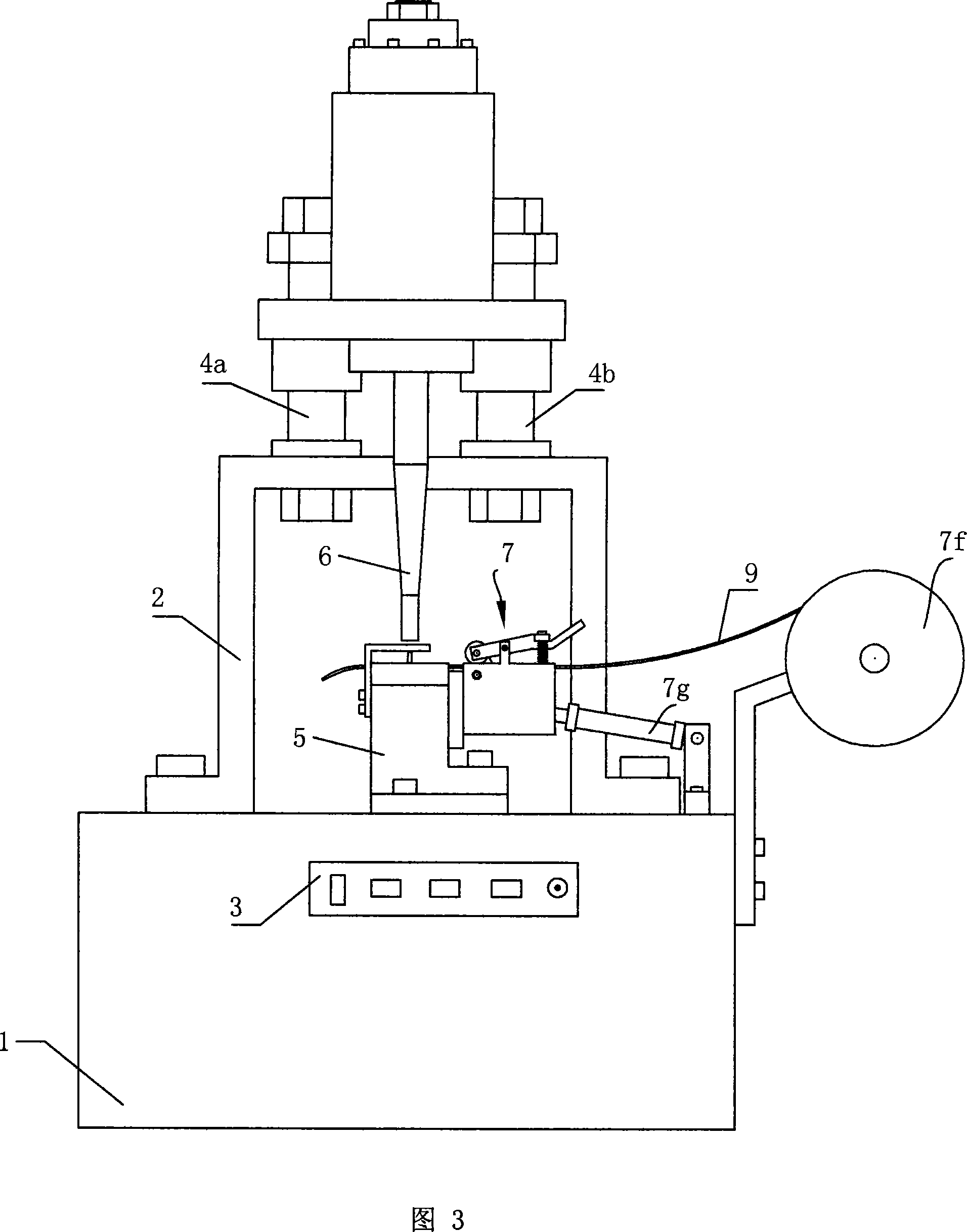
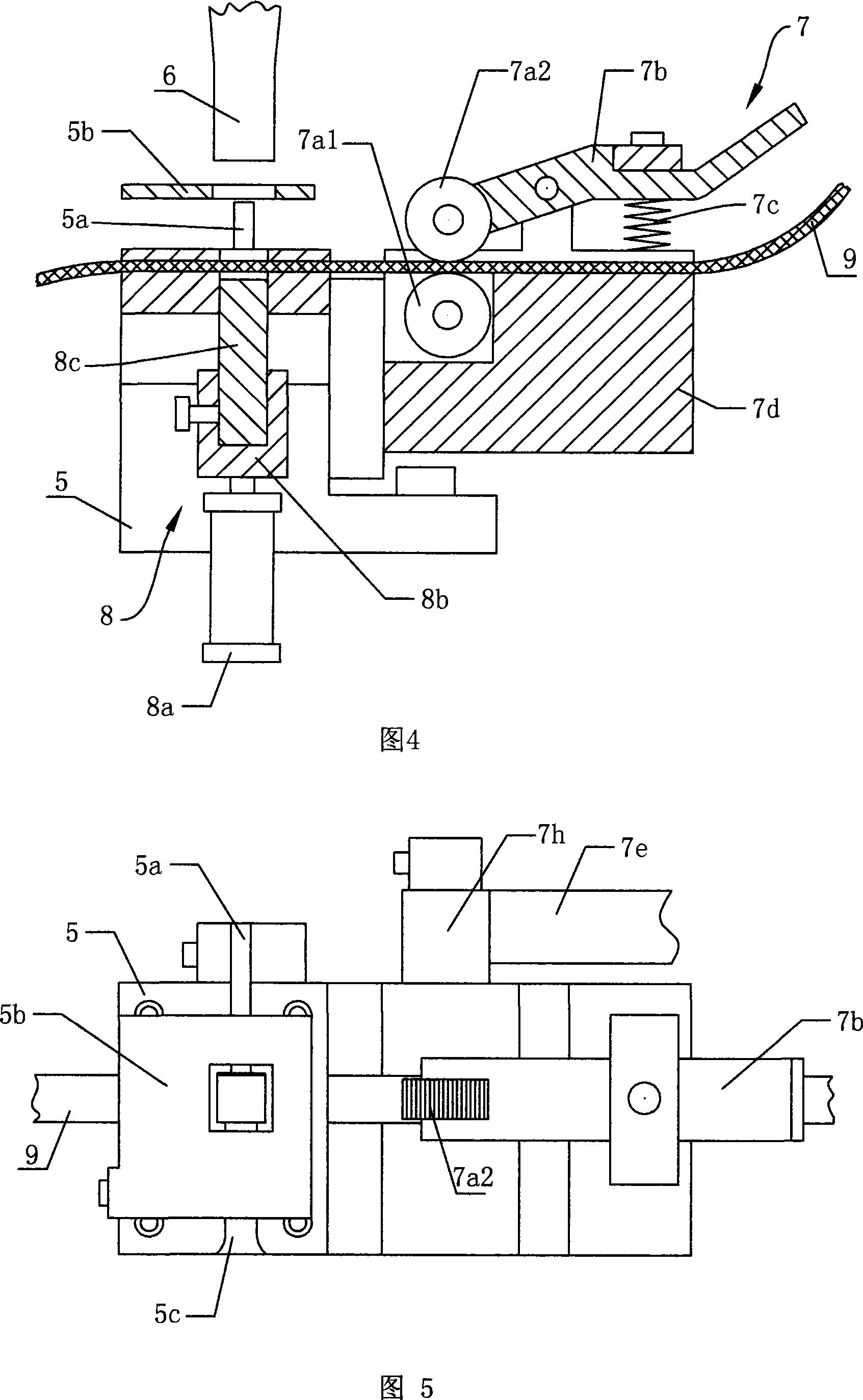
[0028] The zipper buckle welding machine, as shown in Figure 3, comprises a machine base 1, a support 2 fixed on the top of the machine base 1, and a workbench 5, and the workbench 5 is provided with a guide hole for cutter guidance in the welding area, A groove 5c that can accommodate a zipper chain is provided on the upper part, and a zipper limiting block 5a is fixed at the end of the groove 5c. It also includes a feeding device 7 for feeding the sheet plastic strip 9 to the welding area of ​​the workbench 5, a cutting device 8 for die-cutting the plastic strip 9 located in the welding area, a guide fixed on the support 2 Columns 4a, 4b, plastic welding head 6 used for welding the die-cut plastic sheet to the end of the zipper tooth chain, slidingly sleeved on the guide column 4a, 4b, the plastic welding head 6 is preferably an ultrasonic plastic welding head , the first power device (not shown in the figure) installed on the bracket 2 for driving the plastic welding head 6...


PUM


Abstract

The present invention discloses a nylon zipper. It includes the following several portions: two zipper strips, two tooth chains which are respectively fixed on the opposite edges of the described two zipper strips, lower stop fastener fixed in the lower end portion of the described two tooth chains and upper stop fastener fixed in the upper end portion of the described two tooth chains. The described upper stop fastener and lower stop fastener are made up by using plastic sheet respectively, the described plastic sheets are respectively welded on the projected surfaces of said two tooth chains. Besides, said invention also provides a zipper stop fastener welding machine and a processing method of said zipper stop fastener.

Description

technical field [0001] The invention relates to the technical field of zippers, in particular to a nylon zipper; the invention also relates to a processing method for a zipper stopper and a molding device for a zipper stopper. Background technique [0002] Most of the known zipper stoppers are metal buckles. Because the metal buckle is bent from a metal strip, its two ends are not closed, so the two ends are easy to scratch the clothing close to it. If the zipper is installed on The two ends of the pillow, which do not close the metal buckle, are also prone to trapping human hair. Not only that, when the slider hits the upper stop or the lower stop repeatedly, because the two ends of the metal buckle are not closed, the metal buckle is easily opened, causing the slider to slip off from the tooth chain. [0003] There is also a buckle made of nylon material, which is injection-molded between the upper and lower surfaces of two zipper tapes and connects the ends of the two zi...

Claims


Application Information

Patent Timeline
Patent Type & Authority Applications(China)
IPC IPC(8): A44B19/10A44B19/36B29C65/74B29C65/78B29C65/08B29L5/00
Inventor 钟砚宝
Owner 钟砚宝
Why Eureka
Try Eureka