Rotor blade for wind energy plants

A technology for rotor blades and wind energy equipment, which is applied in wind power generation, mechanical equipment, and wind turbines in the same direction as the wind. It can solve the problems of increasing the necessary cost of materials, and achieve the effects of reduced risk, reduced bending stress, and high stability.

Inactive Publication Date: 2007-11-14
NORDEX ENERGY
View PDF7 Cites 11 Cited by
  • Summary
  • Abstract
  • Description
  • Claims
  • Application Information

AI Technical Summary

Problems solved by technology

In addition, the required cost of materials increased

Method used


Image

  • Rotor blade for wind energy plants
  • Rotor blade for wind energy plants

Examples


Embodiment Construction

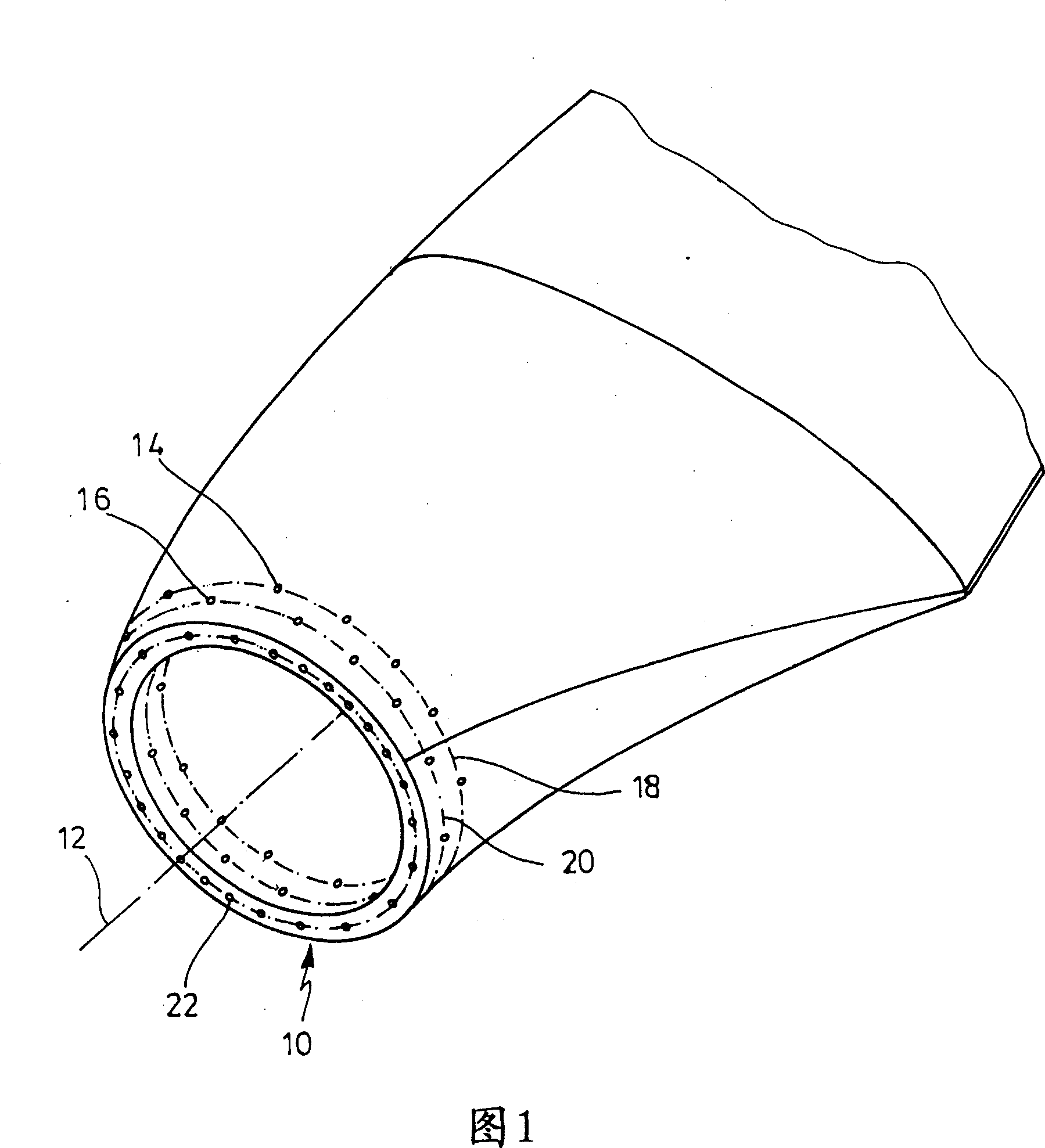
[0025] The blade base of the rotor blade is drawn in FIG. 1 , and the rotor blade consists of two shell halves made of fiber-reinforced plastic material in a manner known per se. On the hub-side end of the rotor blade there is a hub-side rotor blade edge 10 which is formed by an approximately circular annular plane. The width of the ring corresponds to the material thickness of the rotor blade shell in this region. The longitudinal axis of the rotor blade is indicated at 12 . The hub-side rotor blade edge 10 is aligned substantially perpendicular to the longitudinal axis 12 .

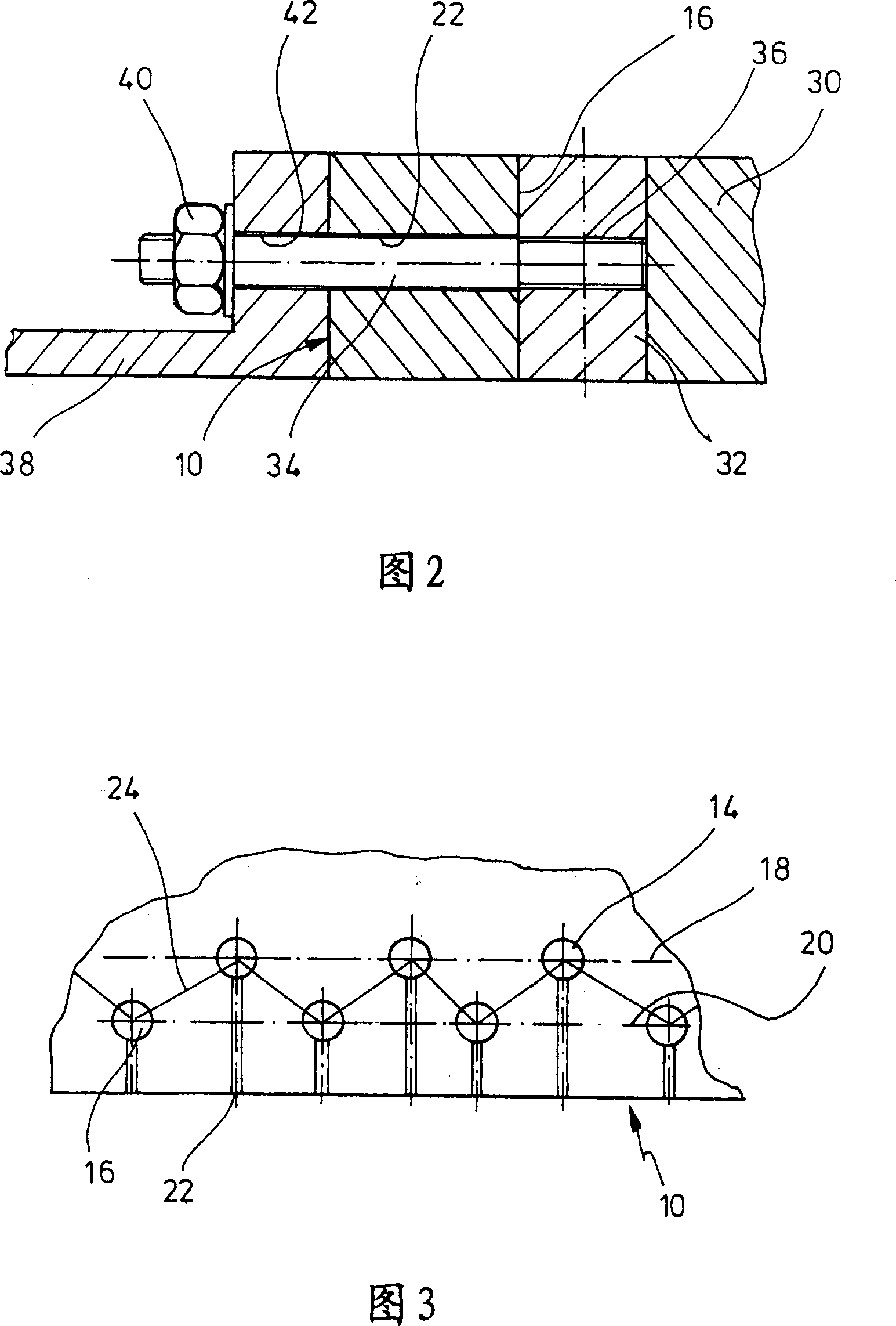
[0026] The rotor blade is provided with a plurality of transverse holes 14 , 16 . In the example shown, the transverse holes 14 , 16 are aligned transversely, approximately perpendicularly, to the longitudinal axis 12 of the rotor blade. However, depending on the shape of the rotor blade and the shape of the rotor blade fastening means 38 (not shown in FIG. 1 ) close to the hub of the wind energy ins...


PUM


Abstract

A rotor blade for wind energy plants with a multiplicity of cross bores running transversely to the longitudinal axis of the rotor blade in the region of the blade base, which are provided for the accommodation of cross pins, wherein for fastening the rotor blade on a rotor blade fixture, tensioning elements act upon the cross pins wherein at least one of the cross bores has a distance from the hub-side rotor blade edge which is different from the distance of a further cross bore from the rotor blade edge.

Description

technical field [0001] The invention relates to a rotor blade for a wind energy installation with transverse holes extending transversely to the longitudinal axis of the rotor blade in the region of the blade base for receiving transverse pins, wherein the rotor blade Fastened to the rotor blade fixture, the tensioning element acts on the transverse pin. Background technique [0002] Such fastening solutions for rotor blades with transverse pins and tensioning elements are well known. In modern wind energy installations, high mechanical loads are present in the connection region between the hub and the rotor blade. These loads increase significantly as wind energy installations become larger and larger. Together with the intended weight-saving construction, this places the highest demands on the construction of the part for mounting the rotor blade. Accordingly, quite a range of different approaches have been devised to improve upon the main principles. [0003] For exam...

Claims


Application Information

Patent Timeline
Patent Type & Authority Applications(China)
IPC IPC(8): F03D1/06
CPCF03D1/0658Y02E10/721Y02E10/72
Inventor J·比克迈尔H·罗赫霍尔茨
Owner NORDEX ENERGY
Why Eureka
Try Eureka