Self-clamping mechanism

A clamping device and clamping technology, applied in the direction of positioning device, clamping, detachable fasteners for friction clamping, etc., can solve the problem of excessive application, use of a lot of energy, and the minimum clamping force of the clamped object cannot be estimated in advance, etc. problem, to achieve the effect of effective power and impact force and energy saving

Inactive Publication Date: 2007-11-14
SHENZHEN ZIJINWANG TECH
View PDF0 Cites 10 Cited by
  • Summary
  • Abstract
  • Description
  • Claims
  • Application Information

AI Technical Summary

Problems solved by technology

The previous clamping devices all need to apply an external force to maintain the clamping force acting on the clamped object, and all previous clamping devices have a common disadvantage: when the external force on the clamped object increases to a certain value, the object will fall It will slide out of the clamping device by itself. At this time, the rough clamping surface usually used on the clamping device often damages the surface of the clamped object, and because the minimum clamping force required by the clamped object is usually unable to be estimated in advance, it is necessary to clamp the object Often the clamping device exerts excessive clamping force on the object
Therefore, previous clamping devices not only required the use of a large amount of energy, but were only effective to a limited extent

Method used


Image

  • Self-clamping mechanism
  • Self-clamping mechanism
  • Self-clamping mechanism

Examples


Embodiment Construction

[0028] The present invention will be further described below in conjunction with the accompanying drawings and embodiments.

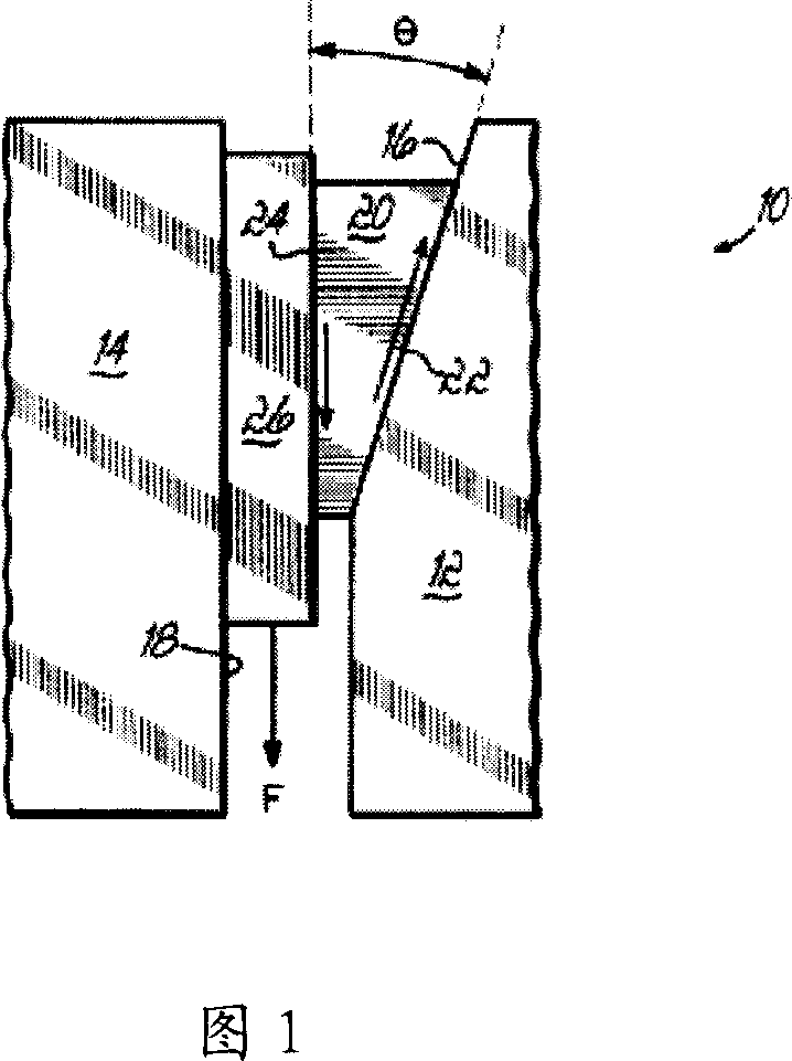
[0029] Referring to FIG. 1 , it is a schematic diagram of the principle of a clamping device of the present invention. This invention series utilizes the relative frictional force between the clamping device and the clamped object to realize the clamping effect on the clamped object in the form of spontaneous energy. In Figure 1, this clamping device uses a sliding wedge to optimize the friction of the device. The greater the external force on the clamping device, the tension generated by the clamping device on the clamped object and the supporting surface A in two directions bigger. One side of the clamped object is supported by the supporting surface B, and the other side is subjected to the extrusion tension given by the clamping block member. At the same time, the reverse force of the supporting surface A on the clamping member is also transmitted ...


PUM


Abstract

The invention relates to a clamping apparatus. The clamping apparatus comprises a support and a clamping element. The clamping member has a surface a in sliding confronting engagement with the support surface A, and a second surface b for engaging the surface of an object to be clamped by the mechanism. The first and second surfaces of the clamping member are disposed at a predetermined angle, theta, is defined by inequality (K+tan(theta)) / (1+Ktan(theta)) is less than or equal to M, formula M represents coefficient of friction of rest between fastening motion element and clamped object, K represents a coefficient of friction of rest between fastening motion element and A supporting plane. The clamping apparatus can clamp objects regardless of static, motility or force of impact applied to the objects, and the clamping apparatus does not require or scarcely require applying energy and not happen exorbitance fastening motion or clipping loosely objects. The clamping apparatus can be extensive use in mechanical layout, machining and manufacturing sector, also can be use in rail facility, bridge and farmery field.

Description

【Technical field】 [0001] The invention relates to a clamping device, in particular to a clamping device for fastening or connecting objects, which can be widely used in mechanical design, processing and manufacturing, and can also be applied and promoted in fields such as railways, bridges and buildings. 【Background technique】 [0002] Clamping devices have been widely used to fasten or connect objects. The previous clamping devices all need to apply an external force to maintain the clamping force acting on the clamped object, and all previous clamping devices have a common disadvantage: when the external force on the clamped object increases to a certain value, the object will fall It will slide out of the clamping device by itself. At this time, the rough clamping surface usually used on the clamping device often damages the surface of the clamped object, and because the minimum clamping force required by the clamped object is usually unable to be estimated in advance, it...

Claims


Application Information

Patent Timeline
Patent Type & Authority Applications(China)
IPC IPC(8): F16B2/00B25B23/12B23Q3/06B23Q3/12
Inventor 刘凤翼刘凤羽洪新瑞刘洪伟
Owner SHENZHEN ZIJINWANG TECH
Why Eureka
Try Eureka