
End-engaging clutch

A clutch and end face technology, applied in the field of clutches, can solve the problems of inconvenient maintenance, wear of the pressure plate and friction plate, short service life, etc., and achieve the effects of high bonding reliability, overcoming easy slippage, and convenient operation.

Inactive Publication Date: 2007-11-14
李卫华
View PDF0 Cites 11 Cited by
  • Summary
  • Abstract
  • Description
  • Claims
  • Application Information

AI Technical Summary

Problems solved by technology

[0003] The mechanical friction clutch is simple in structure, cheap in price, easy to use, easy to operate, and indeed inexpensive, but because it transmits power by friction, it has unavoidable defects. When the transmission torque is large or it is used for a long time, the friction plate Between the fixed plate and the friction plate, between the pressure plate and the friction plate, there will be wear and tear, which will affect the normal power transmission, so the friction clutch should be adjusted or the friction plate should be replaced from time to time. From this point of view, the mechanical The friction clutch has the disadvantages of short service life and inconvenient maintenance

Method used


Image

  • End-engaging clutch
  • End-engaging clutch

Examples


Embodiment Construction

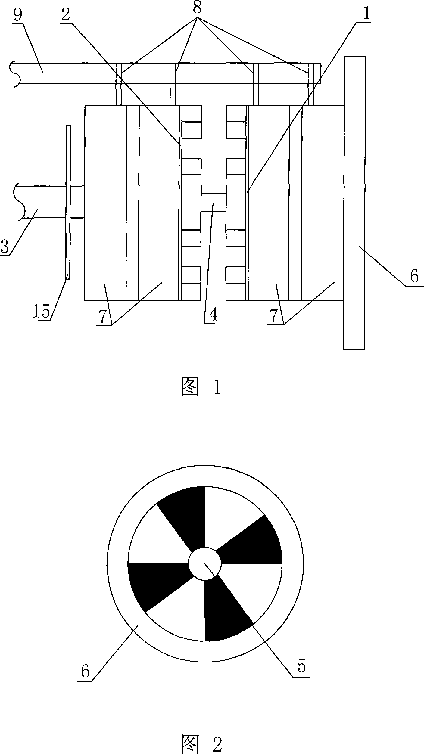
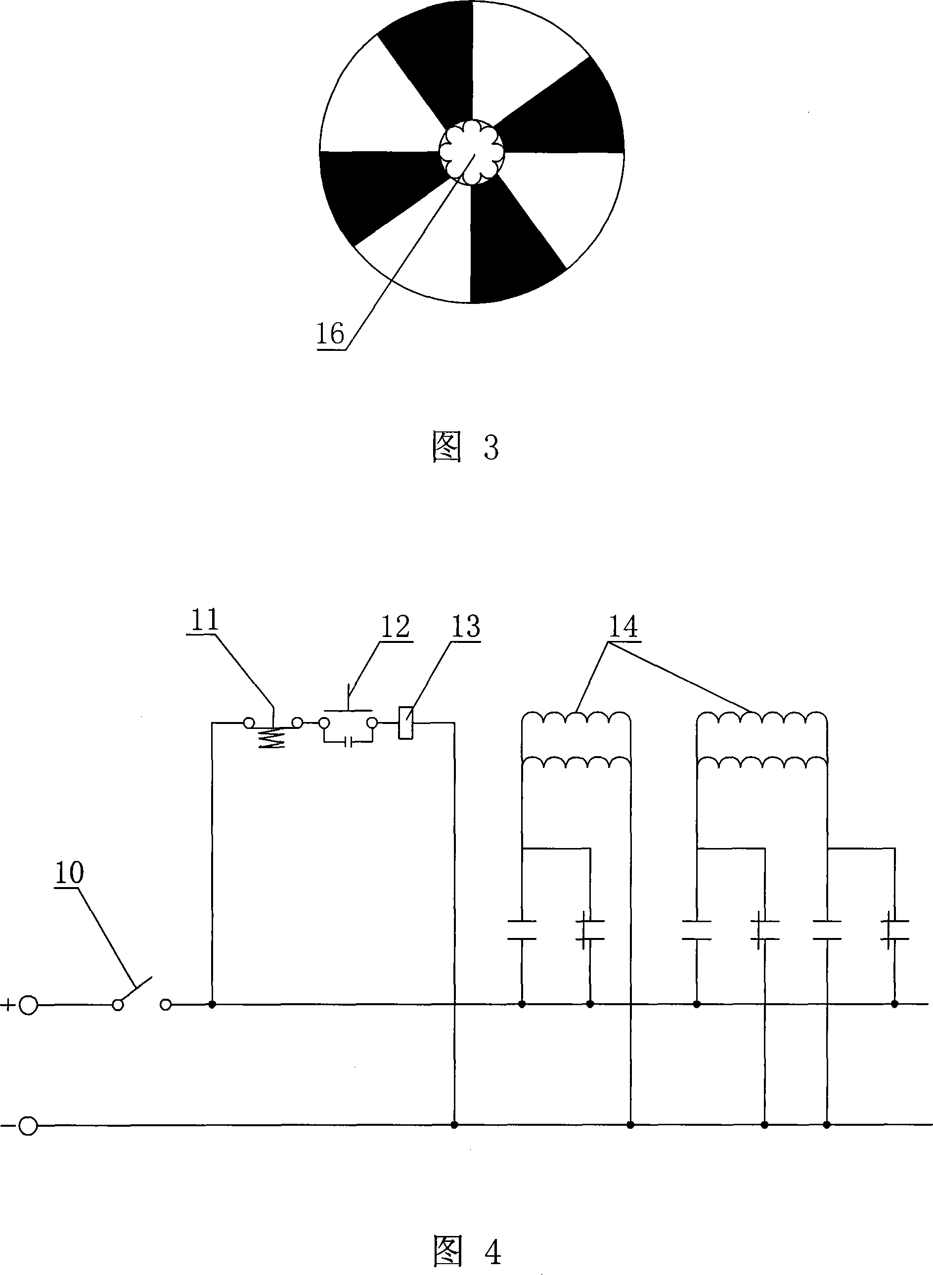
[0022] In the embodiment of the present invention shown in Figure 1, the two main parts of the end face clutch are a circular steel fixed meshing disc 1 and a movable meshing disc 2, the central shaft hole of the movable meshing disc 2 is a spline groove 16, and the movable meshing The spline groove 16 of disc 2 is movable set with the spline output shaft 3 of the gearbox that is arranged horizontally, and the output shaft 3 shaft ends are also coaxially lathed with positioning pin 4. The fixed meshing disk 1 and the movable meshing disk 2 are set facing each other. The center of the fixed meshing disk 1 is provided with a positioning hole 5. The positioning pin 4 of the output shaft 3 is installed in cooperation with the positioning hole 5 of the fixed meshing disk 1. After installation, the movable meshing disk 2 is axially concentric with the fixed meshing disc 1 .

[0023] As shown in Figure 1 and Figure 2, the face of the movable meshing disk 2 facing the fixed meshing di...


PUM


Abstract

The present invention discloses a torque transfer clutch engagement End, including fixed meshing plate,mesh with the fixed-line activities face meshing disk and control activities along the axial meshing engagement with the fixed-combination and separation circuit control devices, fixed mesh disk and disk activity relative meshing surface-installed with the mesh face each other tooth Face or trough, fixed disk and meshing engagement activities on the site coaxial circular wound by a circuit-control meshing surface in a magnetic coil, a fixed mesh at the same magnetic disk and disk activity meshing separation, have the opposite when the fixed mesh magnetic disk Meshing and activities set of suction. The invention sovles the traditional friction clutch slipping easily and wear problems, and convenient manipulation, simple structure with high reliability.

Description

(1) Technical field: [0001] The present invention relates to a clutch, in particular to an end meshing clutch. (two) background technology: [0002] Traditional mechanical friction clutches are widely used in the transmission path of motor vehicles, ships, machine tools, etc. The purpose is to transmit the main drive of the engine to the gearbox. The power between the gearbox and the main drive to achieve fast and smooth gear shifting. A commonly used friction clutch is composed of a flywheel, a fixed plate, a pressure plate and a friction plate. The flywheel and the fixed plate are coaxially connected, and the flywheel shaft is externally connected to the engine output shaft. The output shaft of the gearbox moves axially, and a coaxial friction plate is arranged between the pressure plate and the fixed plate, and the friction plate can be a metal friction plate or a plastic friction plate. When the pressure plate is pressed against the fixed plate, that is, when the frict...

Claims


Application Information

Patent Timeline
Patent Type & Authority Applications(China)
IPC IPC(8): F16D27/09
Inventor 李卫华
Owner 李卫华
Learn More