Flame detection device and method of detecting flame

A flame detection device and flame technology, applied in the field of flame devices, can solve the problems of not being able to detect multiple fuels

Active Publication Date: 2007-11-14
FOSSIL POWER SYST
View PDF2 Cites 23 Cited by
  • Summary
  • Abstract
  • Description
  • Claims
  • Application Information

AI Technical Summary

Problems solved by technology

However, the sensors used in this approach are individual discrete components and only allow detection of the total light intensity in a defined spatial region
[000

Method used


Image

  • Flame detection device and method of detecting flame
  • Flame detection device and method of detecting flame
  • Flame detection device and method of detecting flame

Examples


Embodiment Construction

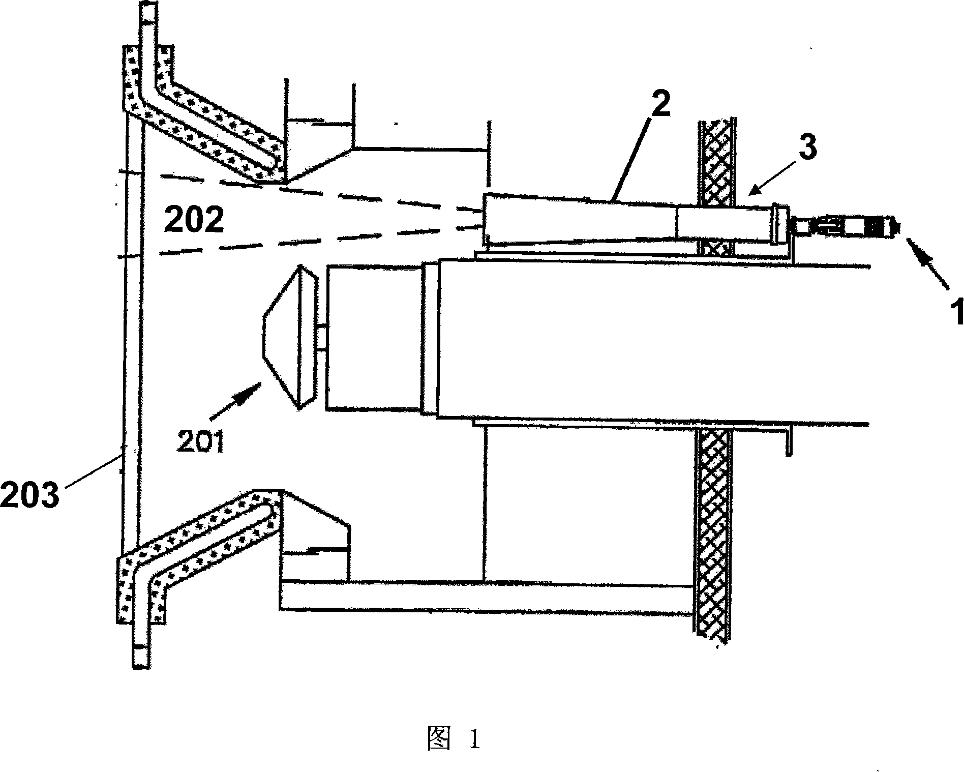
[0027] As shown in FIG. 1 , the flame detection device 1 is arranged at the proximal end of the observation tube 2 . Viewing tube 2 and viewfinder optics associated therewith are constructed using conventional means, such as disclosed in US Pat. No. 5,107,128. As stated therein, the sight tube 2 is arranged in the burner viewing hole 3 of the boiler furnace so that the distal end of the sight tube 2 is close to the flame area 202 produced by the burner 201 . For ease of description, a single burner 201 is shown in FIG. 1 . However, the flame detection device of the present invention can also be applied in multi-burner systems.

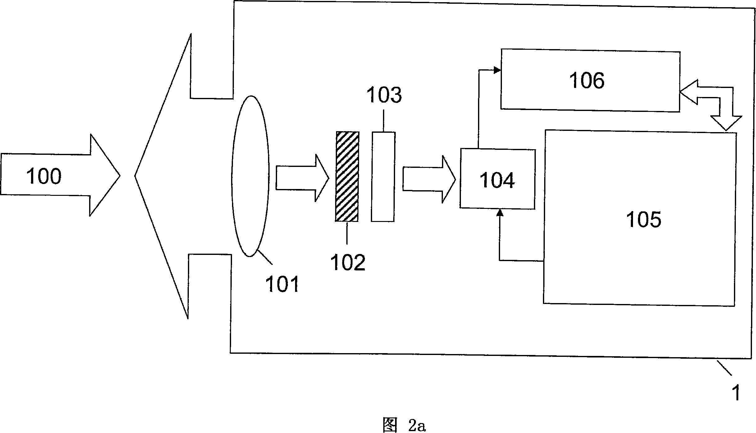
[0028] An exemplary embodiment of a flame detection device 1 according to the invention is described in detail with reference to FIG. 2a. The projected flame 100 represents the flame area 202 within the line of sight of the flame detection device 1 (as seen through the sight tube 2 shown in FIG. 1 ), which includes the flame produced by the burner of...


PUM


Abstract

A device and method for detecting flame using real-time continuous imaging and pattern recognition of infrared (IR) images of a flame region. Infrared emissions radiated from the region pass through a wide field-of-view lens and are detected by a Charged-Coupled Device (CCD) array sensitive to the near IR range. The system then digitizes the image, extracts characteristic parameters from the measurement and stores both the image and characteristic information for pattern recognition. To accomplish the pattern recognition function, the derived real-time characteristics of the current measurement are statistically compared to pre-stored patterns representative of images of radiation emitted from the region while known flame conditions prevail within the region. Based on this comparison, an assessment is made to determine the presence or absence of flame. The characteristic measurements are also used for evaluating the quality of flame.

Description

technical field [0001] The present invention relates to an apparatus and method for detecting flames in furnace and burner systems. More particularly, the present invention relates to an apparatus and method for digitally monitoring the presence or absence of flames in commercial and industrial furnaces in real time. Background technique [0002] A variety of burners are widely used in industrial boilers, such as those used in conjunction with steam turbines used to generate electricity. These burners can burn various fuels, such as coal, oil or gas, and usually have an associated support igniter for the initial combustion of the fuel. In order to ensure that a flame is always present during burner operation, it is necessary to monitor the flame of these burners. In the event that the flame goes out, the burner may continue to supply fuel, which can lead to a potentially dangerous situation. Sometimes, the burner may not ignite when started. Therefore, these situations n...

Claims


Application Information

Patent Timeline
IPC IPC(8): G01C11/00F23M11/04
Inventor 道格拉斯·麦克莱伦
Owner FOSSIL POWER SYST
Why Eureka
Try Eureka