Infrared touch screen and its multi-point touch positioning method

A positioning method and multi-touch technology, applied in the direction of instruments, electrical digital data processing, data processing input/output process, etc., can solve the problems of restricting the use of infrared touch screen, no relative movement, calculation of wrong position coordinates, etc., to achieve Realize the effect of multi-touch positioning, wide application range and simple algorithm

Inactive Publication Date: 2007-11-14
GUANGDONG VTRON TECH CO LTD
View PDF3 Cites 78 Cited by
  • Summary
  • Abstract
  • Description
  • Claims
  • Application Information

AI Technical Summary

Problems solved by technology

This touch detection mode makes the existing infrared touch screen only receive a unique set of position coordinate data within a given period of time, so when there is only one touch point, the touch screen can work normally, for two or more touch points When operating at the same time, the system will calculate the wrong position coordinates, resulting in the reported touch location is not the actual touch location
[0004] Due to the above reasons, the existing infrared touch screen technology will fail in some occasions that need to use multi-touch, such as multiple people playing games at the same time, multiple people writing and drawing at the same time, etc., which greatly limits the application field of infrared touch screen
At present, there are some solutions, such as identifying multiple touch points by detecting the sequence of touch events, but it is easy to occur when there is no relative movement between multiple touch points, and there is no shape and size value of the touch point to refer to. Misjudgment

Method used


Image

  • Infrared touch screen and its multi-point touch positioning method
  • Infrared touch screen and its multi-point touch positioning method
  • Infrared touch screen and its multi-point touch positioning method

Examples


Embodiment Construction

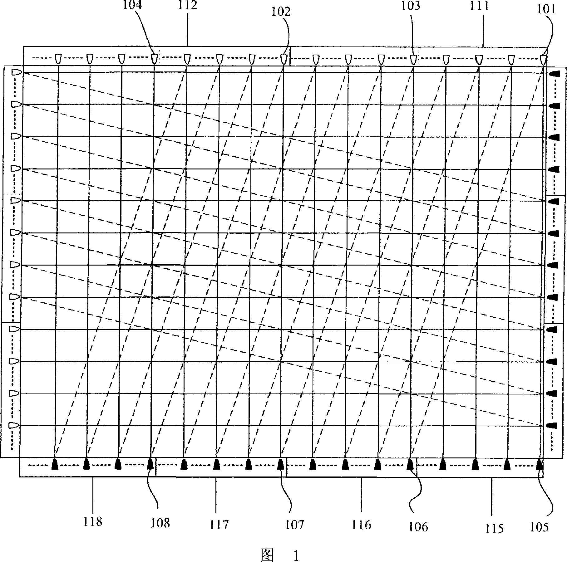
[0056] Fig. 1 is a schematic diagram of the circuit structure of a specific embodiment of the present invention. In the figure, 111, 112 are the emitting circuit boards with infrared emitting elements installed, 101, 103 are infrared emitting elements installed in different positions on the circuit board 111, 102, 104 are infrared emitting elements installed on the circuit board 112, wherein The installation position of 101 on 111 is the same as that of 102 on 112, and the installation position of 103 on 111 is the same as that of 104 on 112. 115, 116, 117, 118 are receiving circuit boards. It can be seen from the figure that the receiving circuit boards 115 and 116 correspond to the transmitting circuit board 111 , and the receiving circuit boards 117 and 118 correspond to 112 in terms of installation positions. Specific to the corresponding relationship between the infrared emitting element and the infrared receiving element, it can be seen that the infrared emitting elemen...


PUM


Abstract

The invention discloses an infrared touch screen and multi-point touch positioning method. That is, at least one touch-screen direction detection, a set of infrared emission scanning circuit corresponding two infrared receiver scanning circuit; a set of infrared emission scanning circuit of an infrared launching the beam of light emitted by the components of a scanning infrared receiver circuit in an infrared receiver components of the receiver at the same time, in the receiving area also receive another set of infrared scanning circuit components of the receiver to receive an infrared detection in infrared touch screen The algorithm process that could be used to determine in advance the scope of touch point touch-point detection algorithm module. The present invention generally use the touch position detection algorithm is a touch location coordinates point to touch another pre-detection algorithm to determine touch point in the region, in combination with detection algorithm is usually the touch location coordinates. The invention can identify two or more touch operation, while more effective identification can touch position.

Description

【Technical field】 [0001] The invention relates to an infrared touch screen, in particular to an infrared touch screen capable of distinguishing multiple touch points and operating simultaneously and a multi-touch positioning method thereof. 【Background technique】 [0002] As an interactive device with simple production process and low production cost, infrared touch screen has been developed rapidly, and has been widely used in many fields. The basic structure of the infrared touch screen is to install several pairs of infrared emitting and infrared receiving elements in a certain order around the edge of a display surface suitable for installation. These transmitting and infrared receiving elements form a transmitting and receiving pair in a one-to-one correspondence, forming a mutually perpendicular transmitting and receiving array along the edge of the display surface, and each pair of transmitting and receiving elements is connected in a certain order under the control o...

Claims


Application Information

Patent Timeline
Patent Type & Authority Applications(China)
IPC IPC(8): G06F3/042
CPCG06F3/04883G06F3/0421G06F2203/04808
Inventor 卢如西周春景李军明
Owner GUANGDONG VTRON TECH CO LTD
Why Eureka
Try Eureka