
Radiating device and radiating system using same

A technology of heat dissipation device and heat dissipation system, which is applied in the cooling of instruments, instrument parts, cooling/ventilation/heating renovation, etc. Effective heat dissipation area, good ventilation, and the effect of improving heat dissipation performance

Inactive Publication Date: 2007-11-14
FU ZHUN PRECISION IND SHENZHEN +1
View PDF0 Cites 8 Cited by
  • Summary
  • Abstract
  • Description
  • Claims
  • Application Information

AI Technical Summary

Problems solved by technology

However, as electronic products continue to develop towards high-density packaging and multi-function, the system space is also reduced, which greatly limits the size of the heat sink, making the heat dissipation problem more and more serious

Method used


Image

  • Radiating device and radiating system using same
  • Radiating device and radiating system using same
  • Radiating device and radiating system using same

Examples


Embodiment Construction

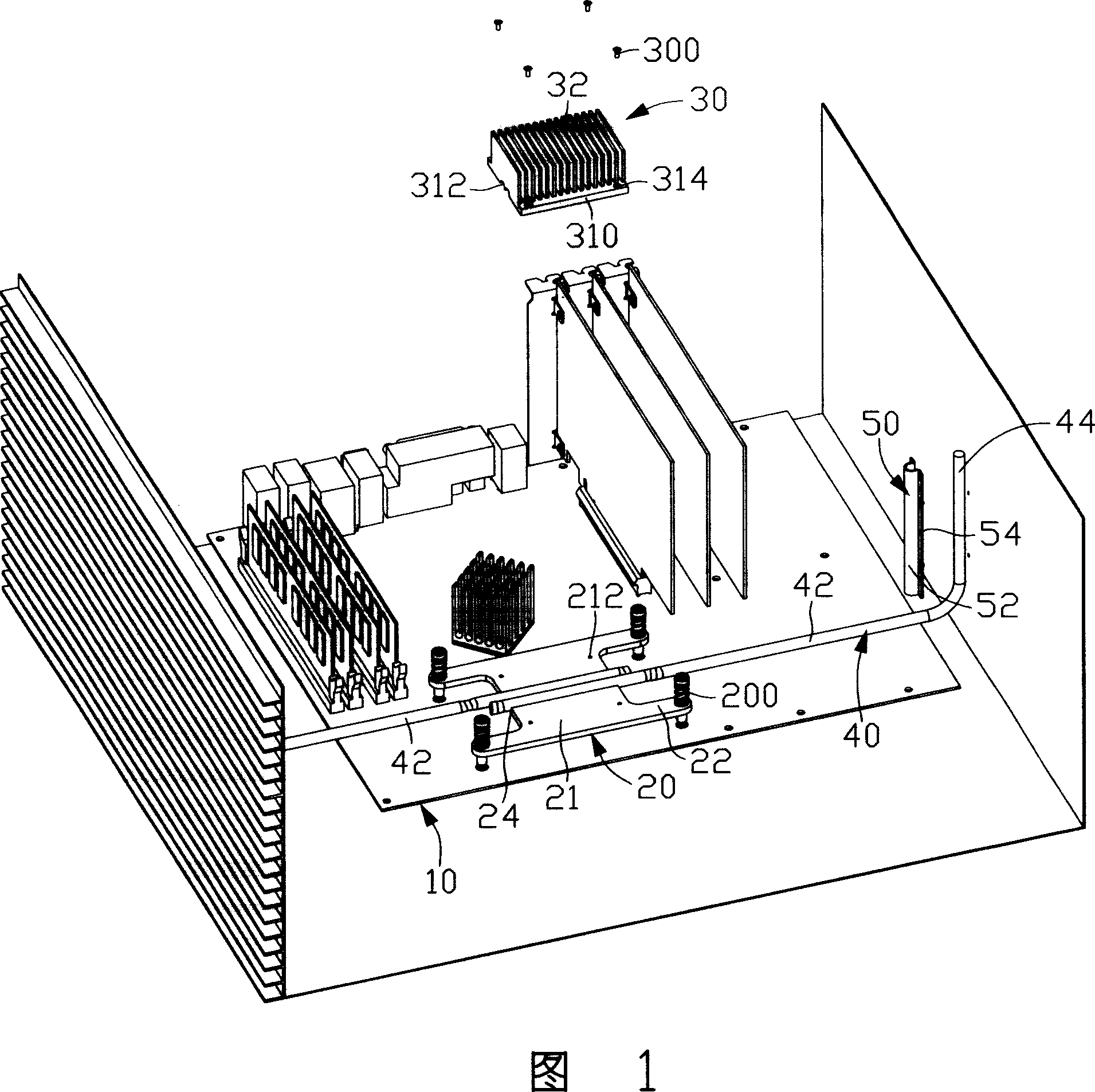
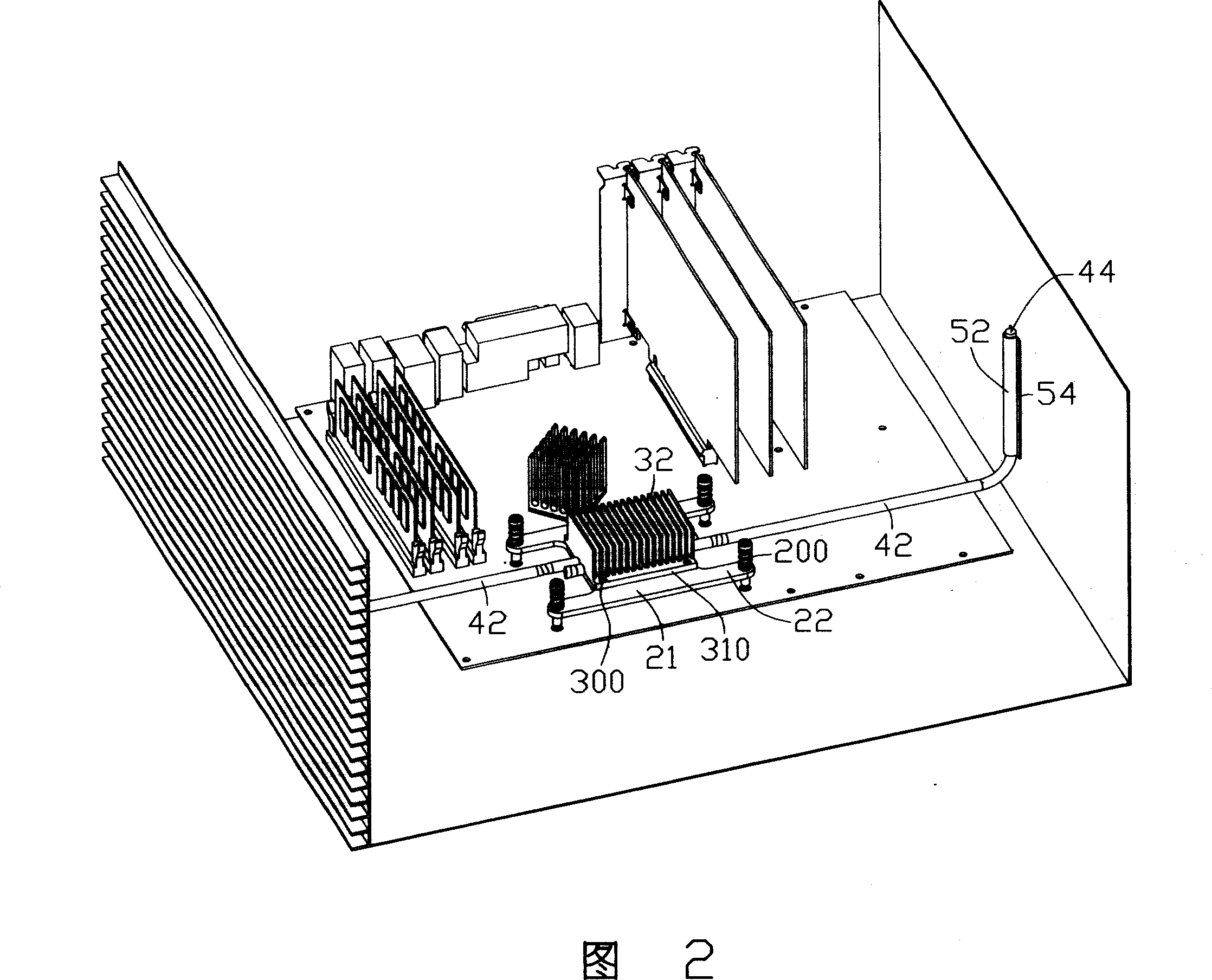
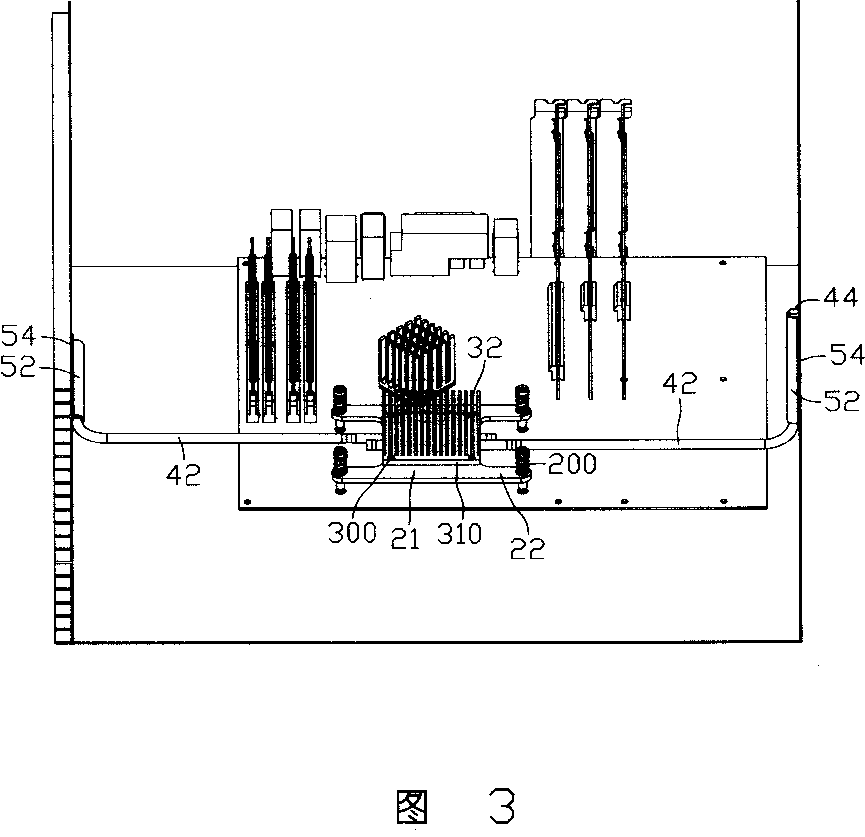
[0012] 1 to 3 show a heat sink in a preferred embodiment of the present invention, the heat sink is used to dissipate the heat generated by the central processing unit (not shown) installed on the motherboard 10, the heat sink mainly includes a A base 20 in contact with the central processing unit, a heat sink 30 mounted on the base 20, two heat pipes 40 with one end interposed between the base 20 and the heat sink 30, and the other ends of the heat pipes 40 being connected to the chassis wall respectively Two connectors 50 on the board.

[0013] The base 20 is generally made of materials with good thermal conductivity such as copper and aluminum, and has a roughly rectangular body 21 whose bottom surface is in contact with the top surface of the CPU to absorb the heat generated therefrom. The four corners of the main body 21 of the base 20 protrude outward respectively with a lug 22 , and each lug 22 is provided with a perforation (not labeled), and the perforation can be use...


PUM


Abstract

The heat sink includes a base seat, a radiator installed on the base seat, and at least a heat pipe. One end of the at least heat pipe is connected to the base seat, and the other end through a connecting piece is connected to chassis. Using heat pipe to connect the base seat to the chassis, the heat sink conducts quantity of heat from the base seat connected to heat source directly to the chassis. Taking full advantage of large volume and good ventilation of the chassis, the invention solves issue of effective area of dissipation for heat sink limited by small system space, increases total effective area of dissipation so as to raise heat dispersion of heat sink.

Description

technical field [0001] The invention relates to a heat dissipation device, in particular to a heat dissipation device for cooling electronic components and a heat dissipation system using the heat dissipation device. Background technique [0002] With the continuous development of the electronic information industry, the operating frequency and speed of electronic components (especially the central processing unit) are constantly increasing. However, high frequency and high speed will increase the heat generated by electronic components, causing their temperature to rise continuously, affecting the performance of electronic components during operation. In order to ensure the normal operation of electronic components, a large amount of heat generated by electronic components must be discharged in time. [0003] For this reason, the industry usually uses a heat sink to dissipate heat from the central processing unit. These existing heat dissipation devices generally include a ...

Claims


Application Information

Patent Timeline
Patent Type & Authority Applications(China)
IPC IPC(8): H05K7/20H01L23/427G06F1/20G12B15/06
CPCH01L23/467H01L2924/0002H01L23/427H01L2924/00
Inventor 余光周大远翁世勋陈俊吉
Owner FU ZHUN PRECISION IND SHENZHEN
Learn More