Heat radiator

A heat dissipation device and heat dissipation fin technology, which is applied in cooling/ventilation/heating transformation, instruments, electrical digital data processing, etc., can solve the problem of increasing the total effective heat dissipation area of ​​heat dissipation devices, small system space, and limiting the effective heat dissipation area of ​​heat dissipation devices, etc. problem, to achieve the effect of increasing the total effective heat dissipation area and improving heat dissipation performance

Inactive Publication Date: 2008-06-04
FU ZHUN PRECISION IND SHENZHEN +1
View PDF0 Cites 6 Cited by
  • Summary
  • Abstract
  • Description
  • Claims
  • Application Information

AI Technical Summary

Problems solved by technology

[0006] The above-mentioned heat dissipation device thermally connects the heat dissipation fins to the shell, and conducts the heat from the heat conduction plate to the shell through the heat pipe, making full use of the advantages of large shell size and direct outward heat dissipation, and solves the problem of limited system space and limited heat dissipation. The problem of the effective heat dissipation area of ​​the device effectively increases the total effective heat dissipation area of ​​the heat sink, thereby improving the heat dissipation performance of the heat sink

Method used


Image

  • Heat radiator
  • Heat radiator
  • Heat radiator

Examples


Embodiment Construction

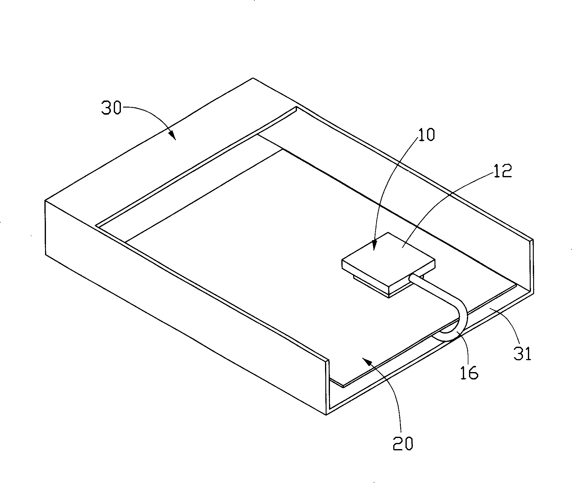
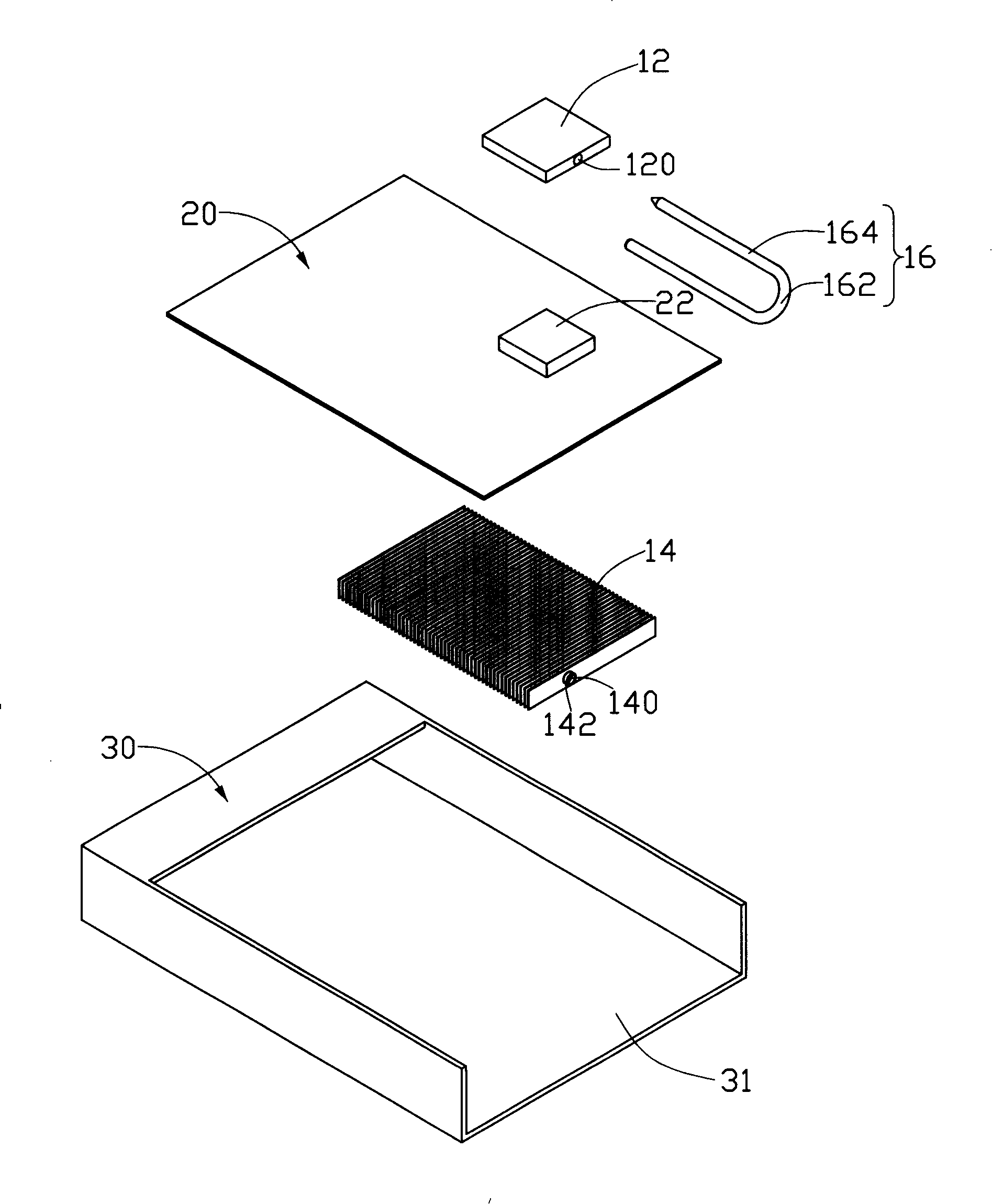
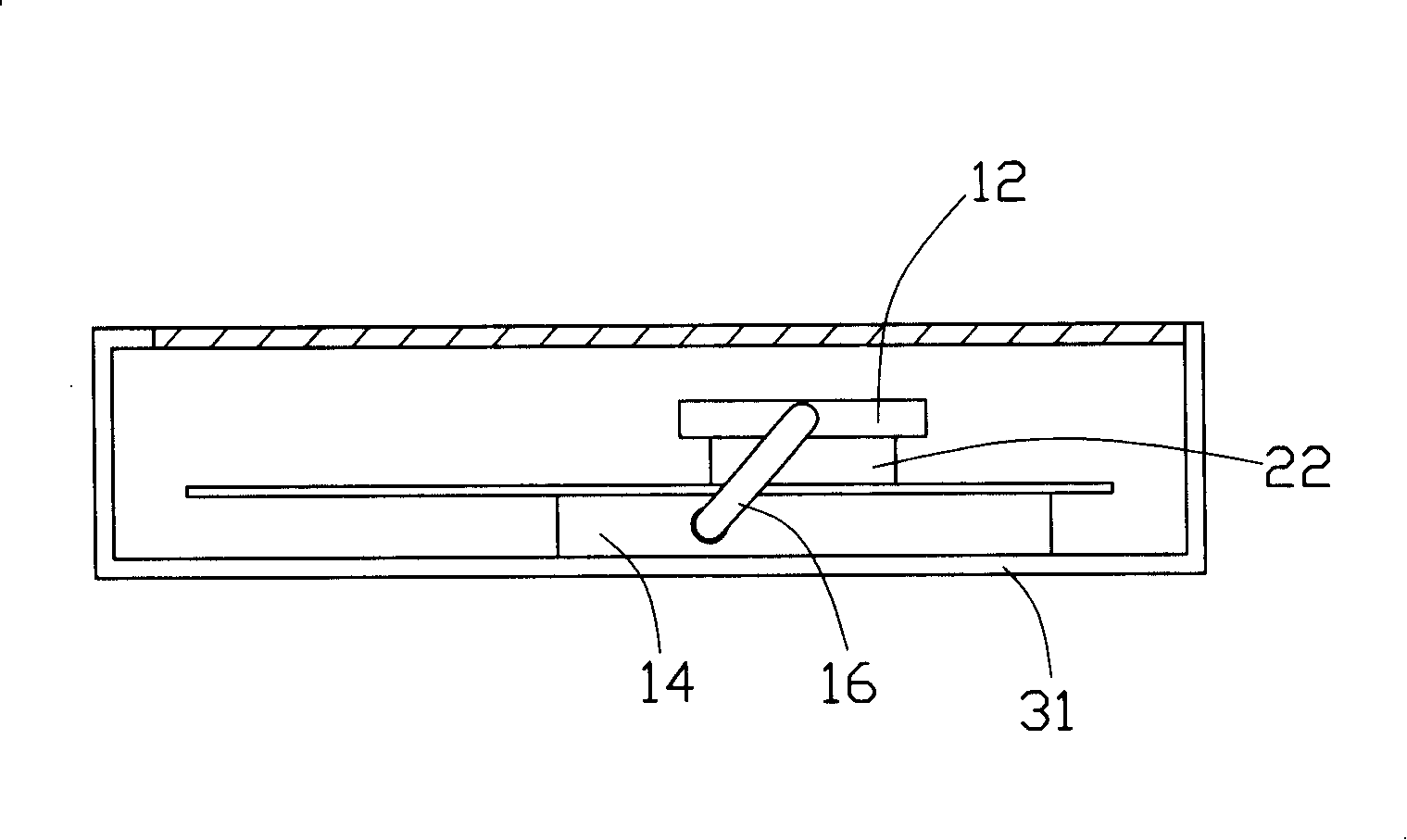
[0011] Figure 1 to Figure 3 A heat sink 10 in a preferred embodiment of the present invention is shown. The heat sink 10 is used to dissipate the electronic components mounted on the front of the circuit board 20. In this embodiment, a central processing unit 22 is used. The circuit board 20 Installed in a housing such as a computer case 30, the heat dissipating device 10 mainly includes a heat-conducting plate 12 in contact with the top surface of the central processing unit 22, a plurality of heat-dissipating fins 14 arranged in parallel on the back of the circuit board 20, and the heat-conducting plate 12 and a heat pipe 16 connecting these radiating fins 14 together.

[0012] The case 30 is made of a metal material with good thermal conductivity and is approximately a rectangular parallelepiped. The case 30 has a bottom plate 31. The circuit board 20 is mounted on the bottom plate 31.

[0013] The heat-conducting plate 12 is generally made of materials with good heat-conducti...


PUM


Abstract

A heat dissipating device is used for cooling the electronic components in an electronic device. The heat dissipating device comprises a heat-conducting plate which is contacted with the electronic components and a heat tube which is connected with the heat-conducting plate; the heat tube is further connected with a plurality of heat dissipating fins which are connected to the shell of the electronic device. The heat dissipating device connects the heat dissipating fins to the shell, conducts the heat of the heat-conducting plate to the shell through the heat tube, making full use of large volume of the shell and direct heat dissipation outward, solving the problem that the effective heat dissipating area for the heat dissipating device is limited due to the small system space, which in turn effectively increases the total effective heat dissipating area for the heat dissipating device, and further improves the heat dissipating performance of the heat dissipating device.

Description

Technical field [0001] The invention relates to a heat dissipation device, in particular to a heat dissipation device for cooling electronic components. Background technique [0002] With the continuous development of the electronic information industry, the operating frequency and speed of electronic components (especially the central processing unit) are constantly increasing. However, high frequency and high speed increase the heat generated by electronic components, causing temperature rise and affecting the performance of electronic components during operation. In order to ensure the normal operation of electronic components, a large amount of heat generated by them must be discharged in time. [0003] For this reason, the industry usually uses a radiator to dissipate the heat of the central processing unit. The existing radiator generally includes a base that is in contact with the central processing unit and a number of heat sinks arranged on the base. The total heat dissi...

Claims


Application Information

Patent Timeline
Patent Type & Authority Applications(China)
IPC IPC(8): H05K7/20H01L23/427G06F1/20
CPCH01L23/427H01L2924/0002H01L2924/00
Inventor 陈永东余光陈俊吉翁世勋
Owner FU ZHUN PRECISION IND SHENZHEN
Why Eureka
Try Eureka