Drawing-plate mechanism for pressure filter and its operation

A filter press and plate pulling technology, which is applied in separation methods, chemical instruments and methods, filtration separation, etc., can solve problems such as two-way decoupling of the pull plate hook, left and right shaking, and synchronization of movement speed, and achieve reliable manufacturing costs. Hook is convenient and the effect of ensuring stability

Active Publication Date: 2007-11-21
杭州兴源环保设备有限公司
View PDF1 Cites 9 Cited by
  • Summary
  • Abstract
  • Description
  • Claims
  • Application Information

AI Technical Summary

Problems solved by technology

Its shortcomings: First, because the filter plate is located on the guide rail through the filter ears on both sides, the two moving speeds cannot ensure their synchronization, so the filter plate shakes from side to side during the movement, which affects the working performance of the whole machine; It adopts the pull plate hook to directly connect with the chain, and it is easy to cause two-way decoupling of the pull plate hook

Method used


Image

  • Drawing-plate mechanism for pressure filter and its operation
  • Drawing-plate mechanism for pressure filter and its operation
  • Drawing-plate mechanism for pressure filter and its operation

Examples


Embodiment 1

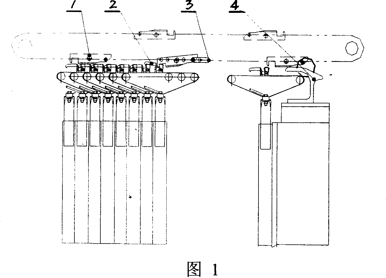
[0014] Embodiment 1: with reference to accompanying drawing 1~6. The pull plate mechanism of the filter press, the claw tongue 2 is a lever structure and is processed and manufactured by the existing technology. The claw tongue 2 is located on the top of the filter plate, and the claw tongue 2 is connected with the claw tongue on the top of the adjacent filter plate. The pull tongue located in the suspension beam There are many pull plate hooks 1 on the plate chain 3 and cooperate with the power arm of the claw tongue 2, and the claw tongue 2 is made of a power arm, a fulcrum and a resistance arm and the head of the resistance arm is a hook structure. The decoupling frame 4 is located below the side of the pull plate chain 3 and there are many pull plate hooks 1 on the pull plate chain 3. The resistance arm of the pull plate hook 1 is lifted by the release frame when it passes through the release frame 4. The upper end of the release frame 4 is curved. shape. The pull plate h...

Embodiment 2

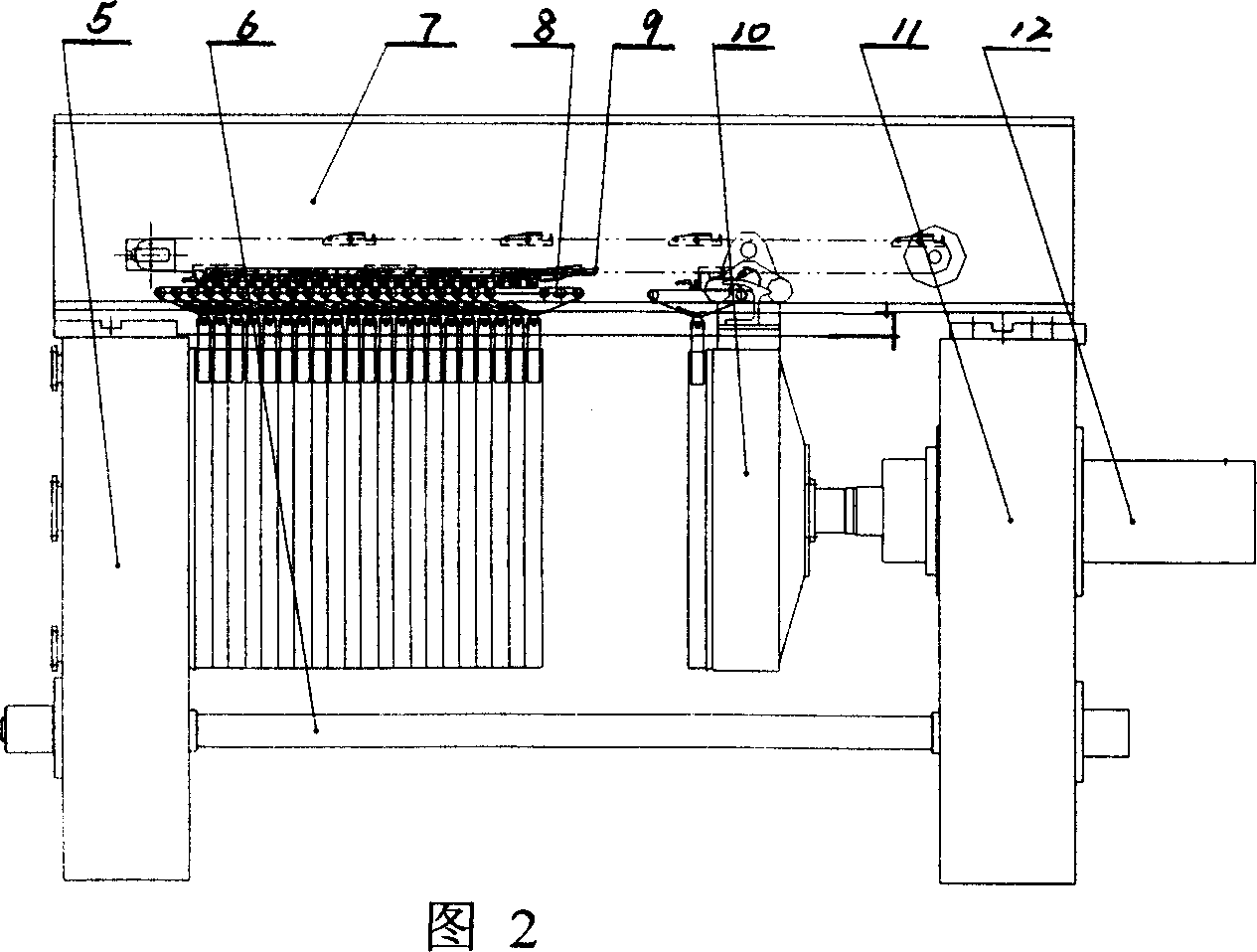
[0017] Embodiment 2: On the basis of Embodiment 1, the working method of the plate pulling mechanism of the filter press, each claw tongue on the filter plate is connected with the claw tongue on the upper end of the adjacent filter plate respectively and forms a suspended automatic Lock the filter plate assembly, there are multiple pull plate hooks 9 on the pull plate chain 8 located in the suspension beam and cooperate with the power arm of the claw tongue, the motor drives the pull plate chain to run counterclockwise, the pull plate hook is on the suspension of the filter plate Slide on the mechanism, when it slides to the last filter plate, it crosses the claw tongue on the suspension mechanism, the pull plate hook falls by its own weight, and meshes with the claw tongue on the suspension mechanism, the power arm of the claw tongue is pressed down by the pull plate hook, The claw hook of the claw tongue is lifted, and the self-locking of the filter plate and the filter plat...


PUM


Abstract

The invention is concerned with the armtie mechanism for press filter and the working method of the armtie mechanism, the jaw assumes lever structure and locates at the top of the filter pad, the jaw hitches with the jaw that is on the top of the neighboring filtering pad, several hooks that is on the chain of the hanging beam assort with the power are of the jaw, the doff hook support locates at one side of the chain that is with several hooks, the resistance arm of the hook uplifts by the doff hook support when it passes the doff hook support. The advantages are: ensures the stability during the movement of the filtering pad; low cost.

Description

Technical field: [0001] The invention relates to a plate-drawing mechanism used for a filter press and a working method of the plate-drawing mechanism, and belongs to the field of filter press component assembly manufacturing. Background technique: [0002] Authorized announcement number CN 2635 176y, name "a filter press puller device", the device is composed of a puller device and a shaker device, which is characterized in that the puller device is a driven sprocket (1 ) is linked with the drive sprocket (19) through the chain (13), the chain (13) is placed in the chain groove (14), and one end of the pressure plate (22) is hinged with one end of the cylinder (2) hinged on the frame , the other end is articulated with the connecting rod (23), the connecting rod (23) is articulated with the bottom plate (24), the pin shaft (21) is fixed on the pull plate hook (6), and the decoupling plate (3) is fixed on the pressing plate (15) On the handle, one end of the pull plate hook...

Claims


Application Information

Patent Timeline
Patent Type & Authority Applications(China)
IPC IPC(8): B01D25/172
Inventor 张景倪国炳孙自忠余坦锋
Owner 杭州兴源环保设备有限公司
Why Eureka
Try Eureka