Optical coupling system for large power laser diode array

A laser diode and optical coupling technology, applied in the field of optical coupling systems, can solve the problems of reducing coupling efficiency, astigmatism, affecting the size of the focused spot and the depth of focus, etc., to achieve the effect of overcoming astigmatism

Active Publication Date: 2007-11-28
HEFEI ZHICHANG PHOTOELECTRIC TECH
View PDF0 Cites 4 Cited by
  • Summary
  • Abstract
  • Description
  • Claims
  • Application Information

AI Technical Summary

Problems solved by technology

The shaper has the characteristics of simple structure, easy processing, and low cost. The disadvantage is that when the Dove prism rotates non-parallel light, it will introduce serious astigmatism. Every last beam of light will produce astigmatism, which will seriously affect the size and depth o

Method used


Image

  • Optical coupling system for large power laser diode array
  • Optical coupling system for large power laser diode array
  • Optical coupling system for large power laser diode array

Examples


Embodiment Construction

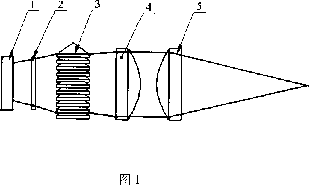
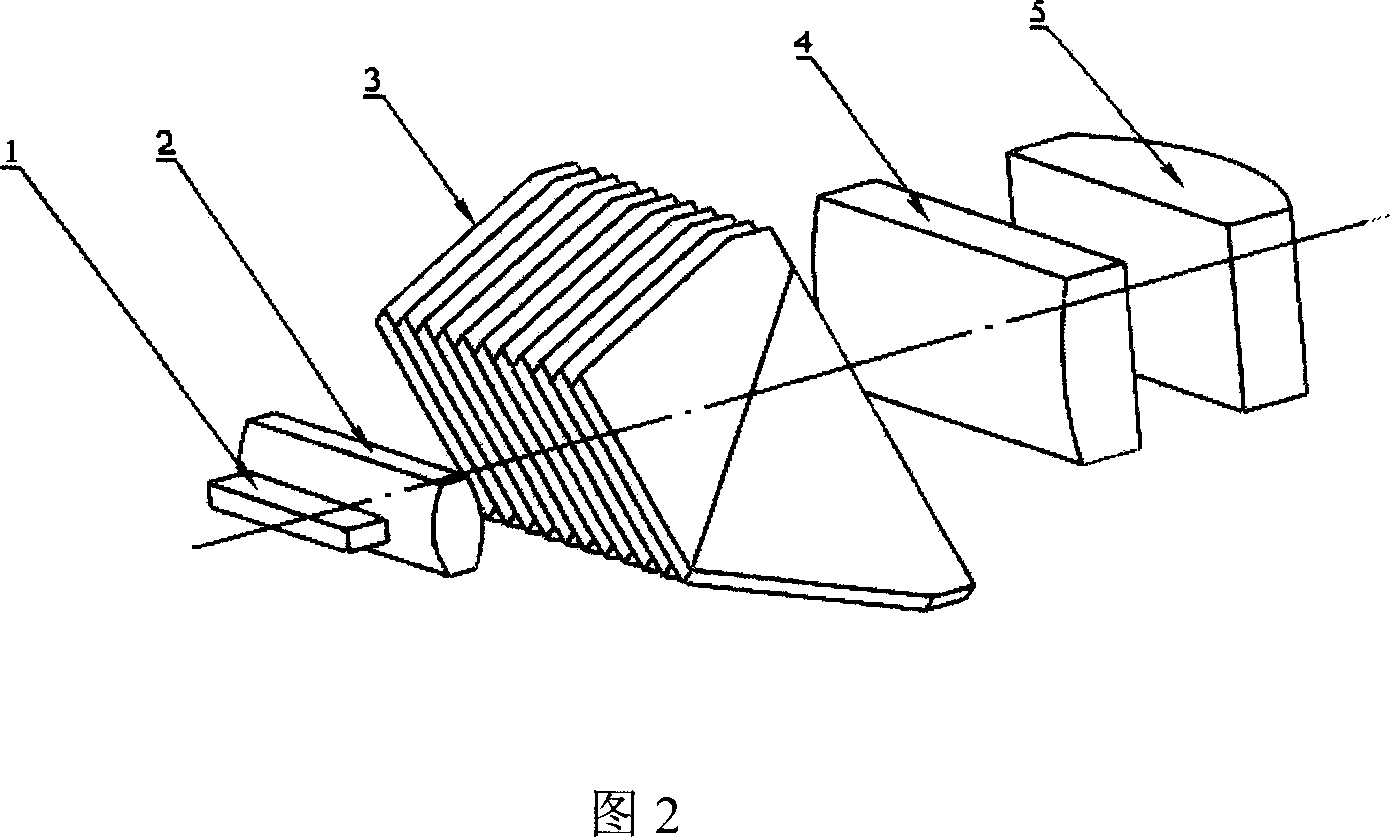
[0019] The present invention will be further described below in conjunction with the embodiments and accompanying drawings, but the protection scope of the present invention should not be limited thereby. Please refer to Fig. 2 first, Fig. 2 is the structural representation of the optical coupling system that the present invention is used for high-power laser diode array, as can be seen from the figure, the present invention is used for the optical coupling system of high-power laser diode array, comprises along the high-power laser diode Micro-cylindrical lens 2 arranged in sequence in the advancing direction of the light beam emitted by array 1, shaper 3, first cylindrical lens 4 and second cylindrical lens 5, it is characterized in that described shaper 3 is made of Biechan prism sheet Closely arranged Bechan prism microchip shaper, the optical axis of each Bechan prism is consistent with the direction of light beam advancement and rotated 45° around the optical axis, the fi...


PUM


Abstract

The invention discloses an optical coupling system for large-power laser diode array, which comprises the following parts along luminous beam advancing direction from the large-power laser diode array: microcylinder lens, Bieham prism micropiece shaper, first column lens and second column lens, wherein the Bieham prism micropiece shaper is composed of tightly arranged Bieham prism slices with each optical axle of Bieham prism in consistency with the luminous beam advancing direction, which is rotated by 45 deg around optical axle; the focus of the first and second column lens coincide mutually. The invention can couple the laser of the large-power laser diode array into energy transmitting optical fiber and couple pump of solid laser, which is simple to manufacture and assemble with high coupling efficiency without changing the transmitting direction of luminous beam.

Description

technical field [0001] The invention relates to a set of optical coupling system capable of splitting, rotating and shaping the beam emitted by a high-power laser diode array, which can couple the laser emitted by the high-power laser diode array into an optical fiber, and can also be used as a pump for a solid-state laser coupling system. Background technique [0002] The light-emitting surface of the laser diode array is mostly a rectangle of 1×100 μm to 1×400 μm, and the emitted laser beam has different divergence angles in two directions: along the length direction is the slow axis, and the divergence angle is usually 10 degrees; The direction parallel to 1 micron is called the fast axis, and the divergence angle is usually 38 degrees. A high-power laser diode array is formed by discontinuously arranging several such light-emitting areas in a linear shape, usually reaching 1 cm in the length direction. It is not difficult to calculate that the Lagrangian invariants of ...

Claims


Application Information

Patent Timeline
IPC IPC(8): G02F1/35G02B27/00
Inventor 孟俊清陆雨田陈卫标
Owner HEFEI ZHICHANG PHOTOELECTRIC TECH
Why Eureka
Try Eureka