Transmission type film test card for camera test and its usage method

A transmissive, test card technology, applied in the field of test cards

Inactive Publication Date: 2007-11-28
深圳市合力泰光电有限公司
View PDF0 Cites 18 Cited by
  • Summary
  • Abstract
  • Description
  • Claims
  • Application Information

AI Technical Summary

Problems solved by technology

It can be seen from the above test methods that if you want to test multiple items, you must use different test cards, and you need to constantly replace and adjust them during the test.
In addition, some projects cannot directly see the effect, such as the measurement of the field of view of the module, it is necessary to use a standard

Method used


Image

  • Transmission type film test card for camera test and its usage method
  • Transmission type film test card for camera test and its usage method
  • Transmission type film test card for camera test and its usage method

Examples


Embodiment Construction

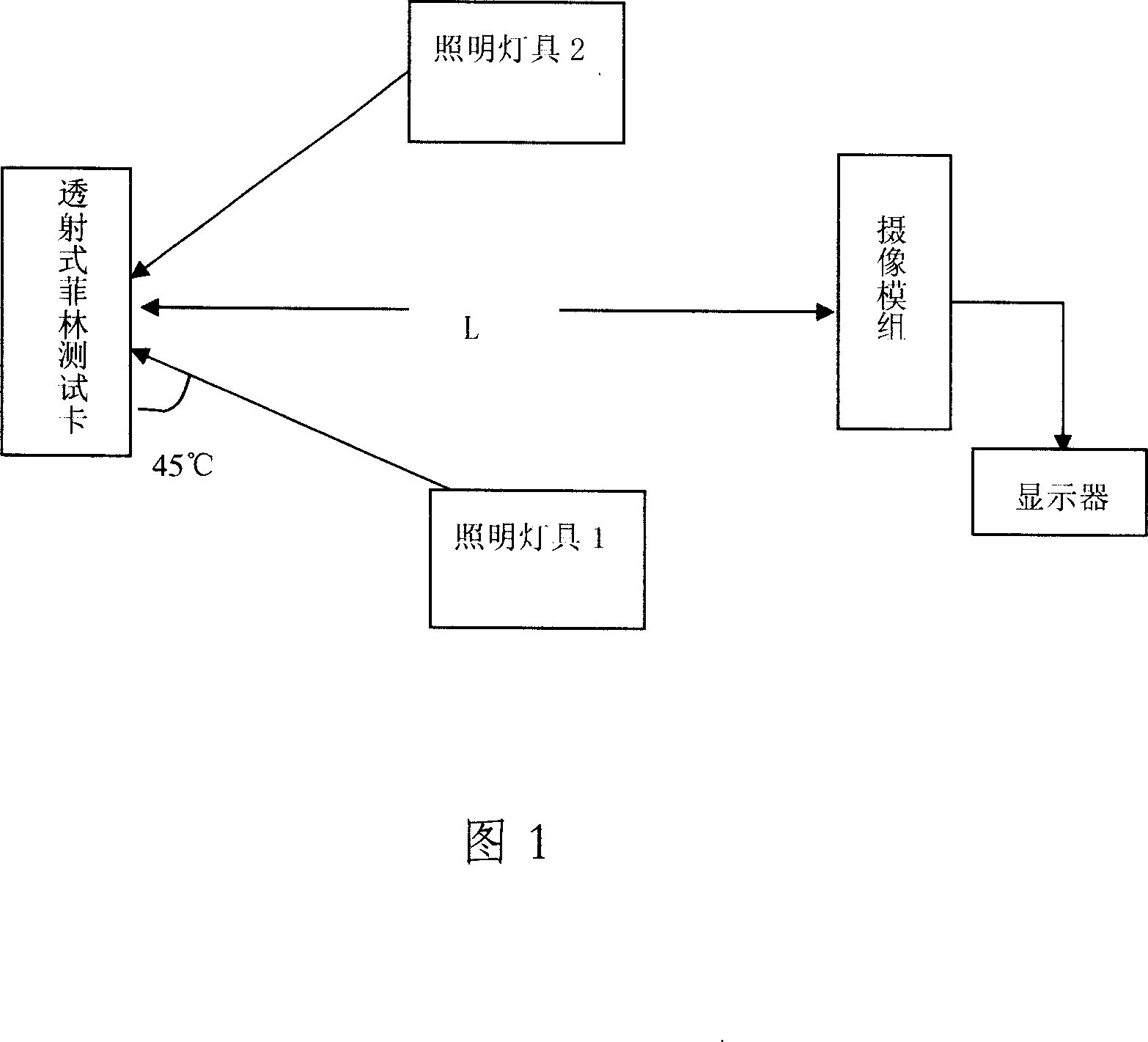
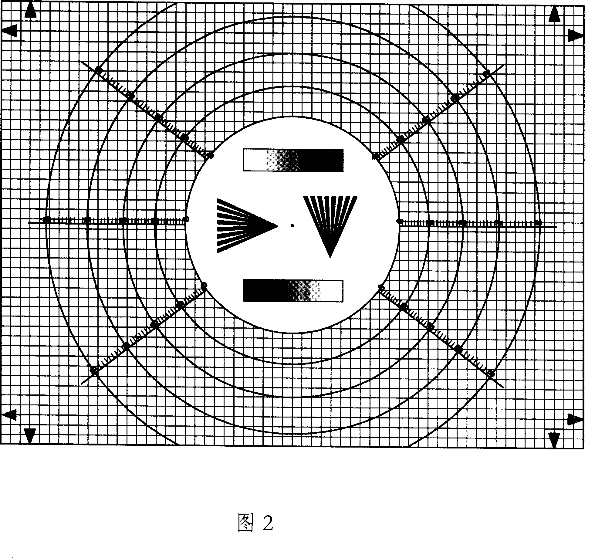
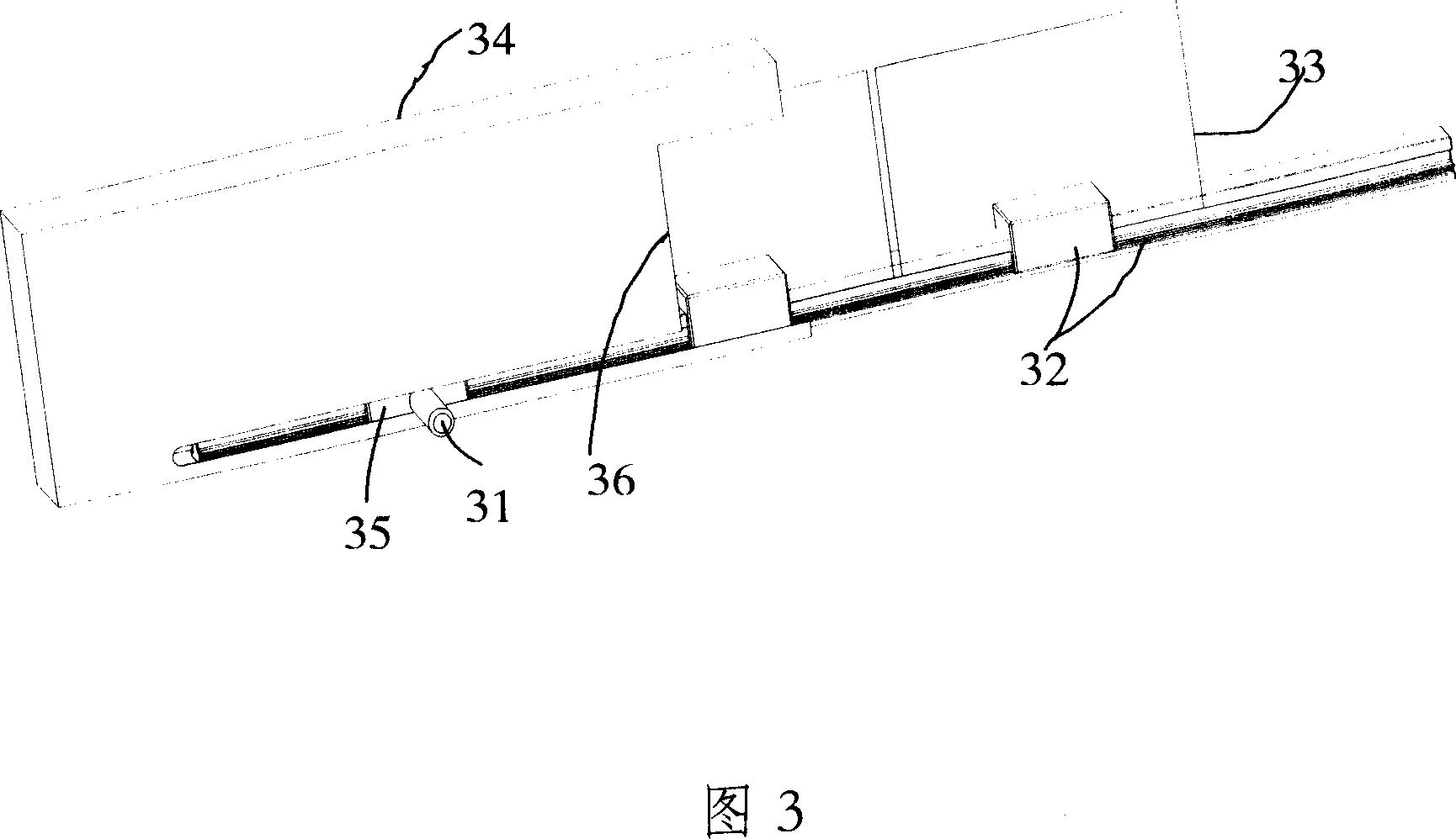
[0023] See Figure 1, Figure 2, Figure 3.

[0024] The surface pattern of the transmissive film test card in the embodiment is a grid. There are several concentric circles on the background. There are digital scales in the horizontal and diagonal directions. The center with the role of positioning point is the center of the concentric circles. Two fan-shaped line patterns for resolution detection. There is a nine-grid test grayscale bar above and below the center of the circle. The colors of the grayscale bars are arranged in reverse order. The fan-shaped line pattern and the test grayscale bar are located in the innermost circle. Inside, there is no grid pattern in the innermost circle, and there are positioning indicators on the four sides. The grid background is black straight lines criss-crossed vertically, horizontally and vertically distributed symmetrically around the central positioning point (ie, the center of the circle), and the distance between rows and columns is e...


PUM


Abstract

The invention discloses a penetrance type filling test piece to test cam and using method, which is characterized by the following: setting the surface of the test piece as cell; arranging several concentric circles on the background; arranging digital scale on crosswise and diagonal direction; setting the center of positioning point as the center of concentric circle. This invention can finish above two optical experiments one time.

Description

technical field [0001] The invention relates to an optical test method and a test card used therein, in particular to a camera test method and a transmissive film test card used therein. Background technique [0002] At present, the imaging quality requirements of mobile phone cameras are getting higher and higher, and the test items for the optical performance of their modules are becoming more and more sophisticated, among which the optical test card is indispensable. In traditional test methods, reflective flat-panel test cards are mostly used, and each test item needs to be equipped with different patterns of test cards, such as the sharpness test card for testing resolution, the gray scale test card for grayscale, and the Conformity Radiation Star Test Card and more. During the test, it is necessary to take pictures of the test cards for the corresponding purposes, and then analyze the obtained pictures to obtain the required results. Due to the unavoidable difference...

Claims


Application Information

Patent Timeline
IPC IPC(8): G03B43/00G01M11/02H04N5/225
Inventor 姜莉莉刘德华
Owner 深圳市合力泰光电有限公司
Why Eureka
Try Eureka