Method of determining a spatial distribution of magnetic particles

A technology of magnetic particles, spatial distribution, applied in the field of computer programs, which can solve problems such as not being good enough

Active Publication Date: 2007-11-28
KONINKLIJKE PHILIPS ELECTRONICS NV
View PDF1 Cites 13 Cited by
  • Summary
  • Abstract
  • Description
  • Claims
  • Application Information

AI Technical Summary

Problems solved by technology

[0003] A disadvantage of the known methods is that the quality of the images of the examination area resulting from the reconstruction is often not good enough for diagnostics, e.g. in medical applications

Method used


Image

  • Method of determining a spatial distribution of magnetic particles
  • Method of determining a spatial distribution of magnetic particles
  • Method of determining a spatial distribution of magnetic particles

Examples


Embodiment Construction

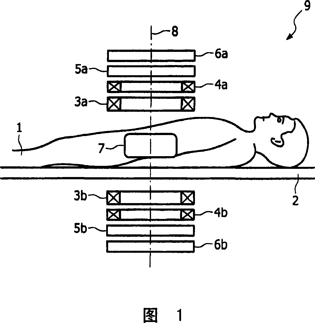
[0032] Figure 1 shows an embodiment of a device 9 according to the invention. Located on the patient display table 2 is an object, which is the patient 1 in the present invention. Located in the patient 1 , for example in the gastrointestinal tract, and in the examination area of ​​the device 9 are magnetic particles for the patient in liquid or granular form. As described below, the size of the examination zone depends inter alia on the magnetic field and magnetic particles used.

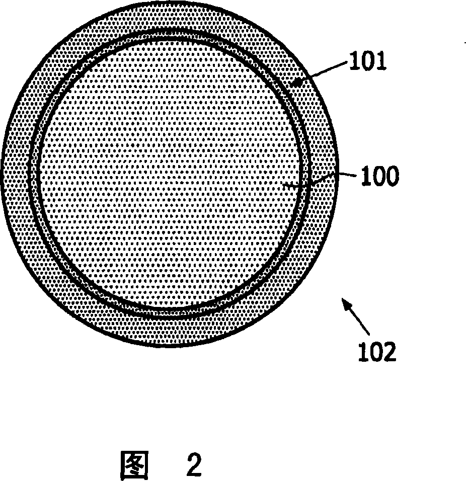
[0033] Figure 2 shows a magnetic particle. It comprises a spherical substrate 100 of eg glass covered with a soft magnetic layer 101 eg 5 mm thick and eg composed of an iron-nickel alloy (eg permalloy). This layer is covered, for example, with a cover layer 102 to protect the particles against acids. The magnetic field strength required to saturate such a particle depends on the particle's diameter. For a diameter of 10 μm, a magnetic field of 1 mT is required for this purpose, whereas for a di...


PUM


Abstract

The invention relates to a method of determining a spatial distribution of magnetic particles in an examination zone, in which a magnetic field is generated that has a first sub-zone of lower magnetic field strength and a second sub-zone of higher magnetic field strength. The positions of the two sub-zones are changed, as a result of which the magnetization in the examination zone changes. Measured values that depend on the change in magnetization are acquired. A reference response function by means of which measured values can be determined mathematically from a spatial distribution of magnetic particles is then determined by means of at least extensive magnetic specimen distribution. Finally, the spatial distribution of magnetic particles is reconstructed from the measured values by means of the reference response function.

Description

technical field [0001] The invention relates to a method for determining the spatial distribution of magnetic particles in an examination zone. The invention also relates to a device for implementing the method according to the invention and a computer program for controlling the device according to the invention. Background technique [0002] The method specified in the opening paragraph is known from DE 101 51 778 . In the method, the magnetic field is first generated in such a way that a first subregion of lower magnetic field strength and a second subregion of higher magnetic field strength are generated in the examination region, i.e. the magnetic field strength in the first subregion lower than the magnetic field strength in the second subzone. Then, the position of the sub-zone space in the examination zone is changed, thereby causing a local change in the magnetization of the particles in the examination zone. From the acquired signals which depend on the magnetiz...

Claims


Application Information

Patent Timeline
Patent Type & Authority Applications(China)
IPC IPC(8): A61B5/05
CPCA61B5/0515A61B5/05A61B5/7257
Inventor B·格莱克J·韦泽尼克T·尼尔森
Owner KONINKLIJKE PHILIPS ELECTRONICS NV
Why Eureka
Try Eureka