IC detecting machine capable of simultaneously multiple parallel built-in testing

A detection machine and insertion technology, which is applied in the direction of electronic circuit testing, electrical measuring instrument parts, measuring electricity, etc., can solve the problems of limited production capacity, multi-exchange displacement time, and multi-time, so as to reduce IC exchange pick-and-place The effect of shifting time, reducing standby time, and increasing productivity

Active Publication Date: 2007-12-05
HON TECH INC
View PDF1 Cites 10 Cited by
  • Summary
  • Abstract
  • Description
  • Claims
  • Application Information

AI Technical Summary

Problems solved by technology

[0005] Due to the above-mentioned IC detection operation, each IC to be tested is first transferred to the transfer mechanism 26 by the left cantilever pick-and-place mechanism 24, and then the IC on the transfer mechanism 26 is transferred to the detection platform 23 by the right cantilever pick-and-place mechanism 25. The inspection operation makes it necessary to go through two exchange procedures during the transportation process, which consumes too much exchange and displacement time. Correspondingly, the IC transportation after the test also needs to go through two exchange procedures. procedures, causing the overall transportation to spend too much time; moreover, the test sockets 231 of each group of test stations 23 can only provide a single IC for testing at a time, even if six groups of test stations 23 are set, they can only test six groups of test stations 23 at the same time. Each IC is tested and tested, so the test capacity that can be carried out is quite limited. If the test time required for each IC is longer, the capacity that the entire inspection machine can achieve is even more limited, which is not enough to meet the current high capacity demand.

Method used


Image

  • IC detecting machine capable of simultaneously multiple parallel built-in testing
  • IC detecting machine capable of simultaneously multiple parallel built-in testing
  • IC detecting machine capable of simultaneously multiple parallel built-in testing

Examples


Embodiment Construction

[0036] In order to enable your examiner to have a further in-depth understanding of the present invention, a preferred embodiment is hereby exemplified and described as follows in conjunction with the drawings:

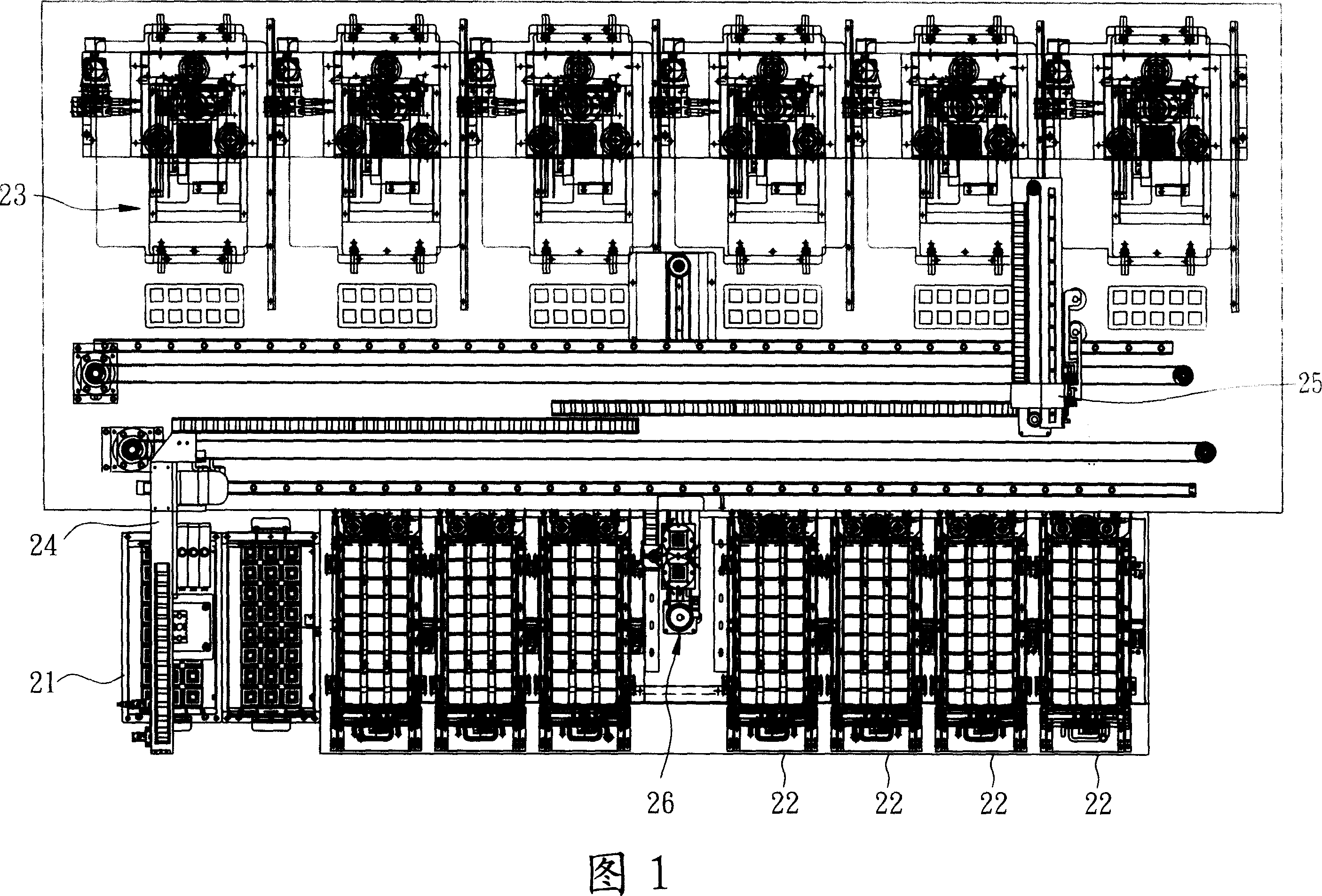
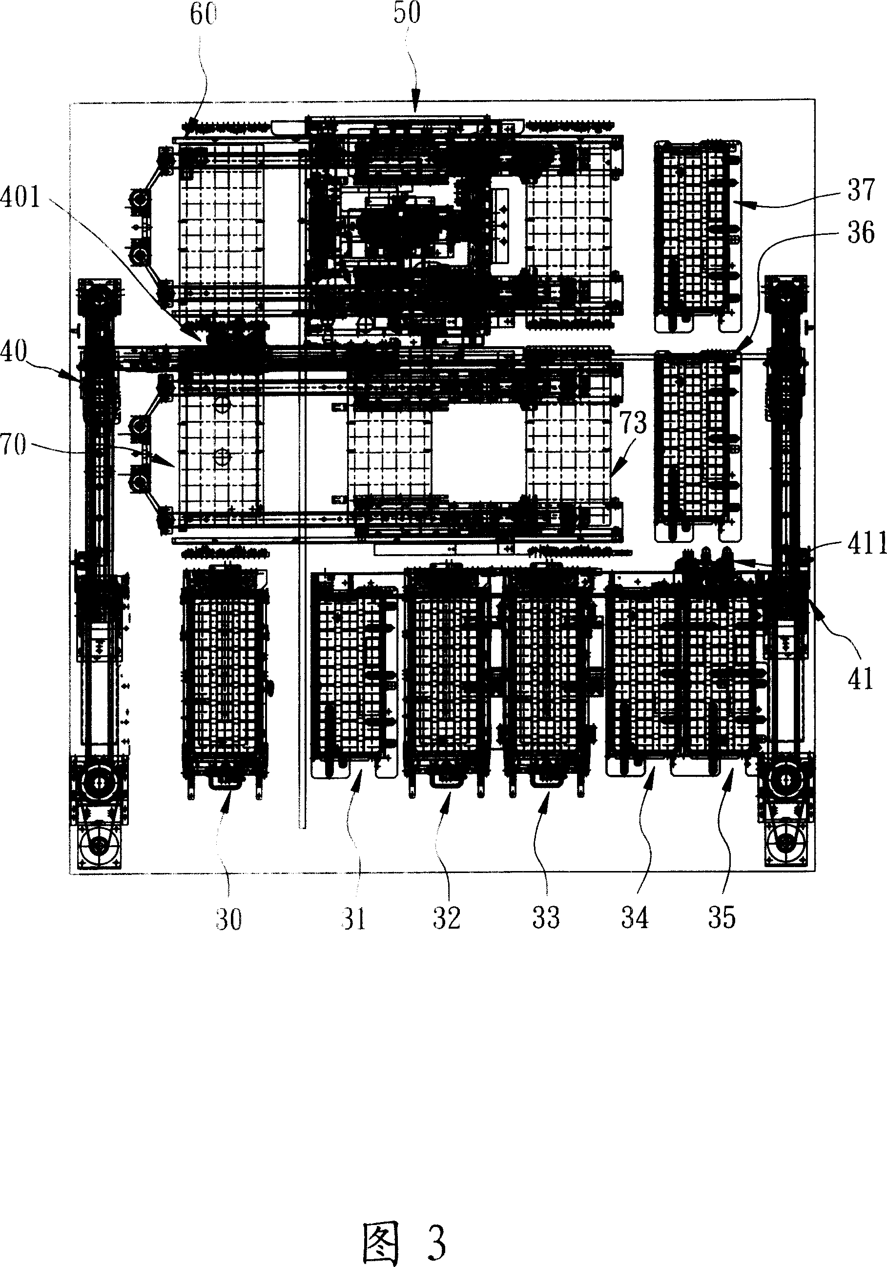
[0037]Referring to Fig. 3 and Fig. 4, the present invention is provided with a liftable supply box 30, a liftable empty box 31, a liftable good product receiving box 32, 33 on the front side and the peripheral side of the machine, and The receiving boxes 34, 35, 36, 37 for defective products are provided with an input terminal IC conveying mechanism 40 on the side of the feeding box 30, and output terminals are provided on the sides of the receiving boxes 34, 35, 36, 37 IC delivery mechanism 41, the input end IC delivery mechanism 40 is provided with a pick-and-place head 401 with several suction nozzles, and the pick-and-place head 401 can be used for the first, second, and third directions (X, Y, and Z axial directions). Displacement, to absorb and displace the IC t...


PUM


Abstract

The invention discloses an IC feeler mechanism to do multiple paralleling particle placements simultaneously, which comprises the following parts: material supplying box, material-receiving box, input end IC transmitting mechanism, output end IC transmitting mechanism, testing part, transmitting tool and orbit transmitting mechanism, wherein the input end IC transmitting mechanism sucks the detected IC on the material supplying box to the transmitting tool to bear multiple particles of the detected IC; the transmitting tool utilizes orbit transmitting mechanism to transmit the transmitting tool into the testing part through orbit, which testes multiple particles of IC to move out the transmitting tool after testing; the output end IC transmitting mechanism classifies each tested IC in the transmitting tool to place in each receiving box. The invention reduces the exchanging, placing and depositing time of IC greatly, which improves the testing property effectively.

Description

technical field [0001] The invention relates to an IC testing machine, in particular to an IC testing machine which can simultaneously transfer multiple ICs to a test port for testing by using a carrying jig and can simultaneously insert and test multiple ICs in parallel. Background technique [0002] Under the continuous research and development and innovation of today's technology, the work that must be completed by the combination of many large electronic circuits in the past has been completely replaced by integrated circuits (IC for short). Since ICs undergo multiple processing procedures in the production process, Therefore, in order to ensure product quality, after the IC production is completed, the merchants will carry out circuit testing operations to detect whether the IC is damaged during the production process, and then detect defective products. [0003] Please refer to Fig. 1, which is the applicant's previous Taiwan Patent Application No. 91210786 "Conveying ...

Claims


Application Information

Patent Timeline
Patent Type & Authority Applications(China)
IPC IPC(8): G01R1/02G01R31/28
Inventor 杨家彰
Owner HON TECH INC
Why Eureka
Try Eureka