
Controllable gas vibrating system

A technology of excitation and gas, applied in the direction of fluid using vibration, etc., can solve the problems of liquid excitation, high cost of electromagnetic excitation, difficult to control, electromagnetic excitation current power restriction, etc., to achieve low cost and controllable frequency. , easy to use effect

Inactive Publication Date: 2007-12-19
INST OF MECHANICS - CHINESE ACAD OF SCI
View PDF0 Cites 6 Cited by
  • Summary
  • Abstract
  • Description
  • Claims
  • Application Information

AI Technical Summary

Problems solved by technology

[0002] The research on earthquake simulation shaking tables has a history of several decades. Among them, the excitation systems used in earthquake simulation shaking tables include gas excitation system, liquid excitation system, and electromagnetic excitation system. However, although the force generated by gas excitation is large, the It is difficult to control, and liquid excitation and electromagnetic excitation are expensive, and electromagnetic excitation is also restricted by current power

Method used


Image

  • Controllable gas vibrating system

Examples


Embodiment Construction

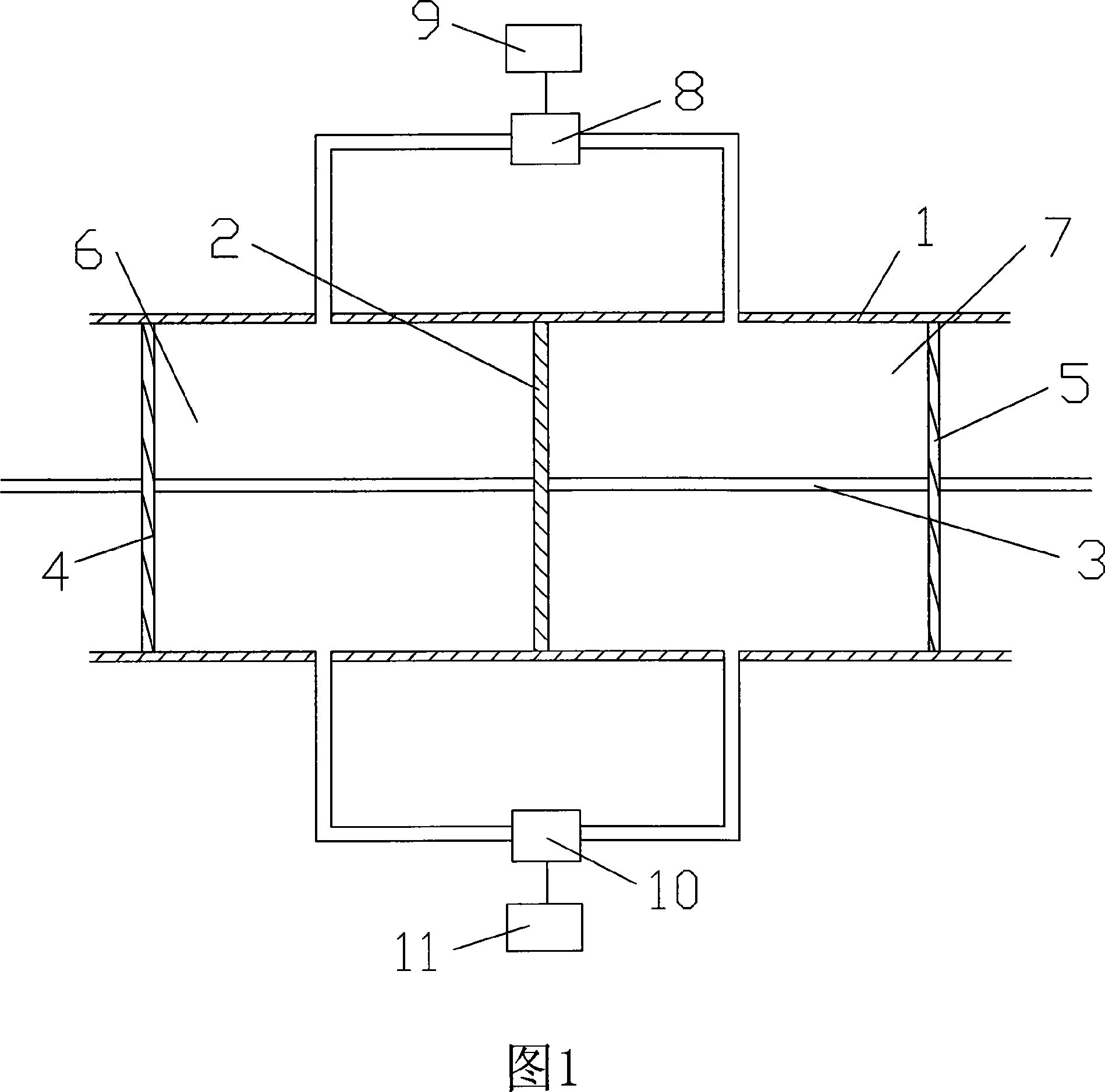
[0008] As shown in Figure 1, the controllable gas vibration excitation system of the present invention includes an excitation cylinder 1, a piston 2, and a guide rod 3. Two partitions 4, 5 are respectively arranged at both ends of the excitation cylinder 1, and the two partitions 4, 5 Matching with the inner wall of the vibration cylinder 1, the inner wall of the vibration cylinder 1 forms a closed space, the piston 2 is set in the closed space, and the guide rod 3 passes through the partition 4, the piston 2, and the partition 5 in sequence, and the piston 2 divides the closed space Be left air chamber 6, right air chamber 7, be provided with air inlet 61, exhaust port 62 on left and left air chamber 6, be provided with air inlet 71, exhaust port 72 on right air chamber 7, air intake Between the ports 61 and 71 there is a ball valve 8 connected to the air source for controlling the intake air, the ball valve 8 is connected to the stepper motor 9, and between the exhaust ports ...


PUM


Abstract

The controllable gas vibrating system includes one exciting barrel, one piston, one guide bar, two baffle plates separately on two ends of the exciting barrel to form one sealed space together with the exciting barrel, ball valves, two motors and one control system to control the rotation of the motors. The piston is set on the guide bar for sliding relatively to the guide bar and inside the sealed space to separate the sealed space into one right gas chamber and one left gas chamber with ball valve controlled gas inlet and gas outlet each. The controllable gas vibrating system has controllable vibrating frequency, low cost and use convenience.

Description

technical field [0001] The invention relates to a controllable gas excitation system for an earthquake simulation vibration table. Background technique [0002] The research on earthquake simulation shaking tables has a history of several decades. Among them, the excitation systems used in earthquake simulation shaking tables include gas excitation system, liquid excitation system, and electromagnetic excitation system. However, although the force generated by gas excitation is large, the It is difficult to control, and liquid excitation and electromagnetic excitation are expensive, and electromagnetic excitation is also restricted by current power. Contents of the invention [0003] The object of the present invention is to provide a controllable gas vibration system with low price and convenient use. [0004] In order to achieve the above object, the technical solution of the present invention is: a controllable gas vibration excitation system, including an excitation c...

Claims


Application Information

Patent Timeline
IPC IPC(8): B06B1/18
Inventor 李岐洪友士葛斐
Owner INST OF MECHANICS - CHINESE ACAD OF SCI
Learn More