

Device and method for applying layers of a powder material onto a surface
A technology of powder material and material conveying device, which is applied in the direction of solid material additive processing, additive processing, and process efficiency improvement, etc., can solve the problems of non-reuse, thermal damage, etc., and achieve the effect of small thermal load
- Summary
- Abstract
- Description
- Claims
- Application Information
AI Technical Summary
Problems solved by technology
Method used
Image

Examples
Embodiment Construction
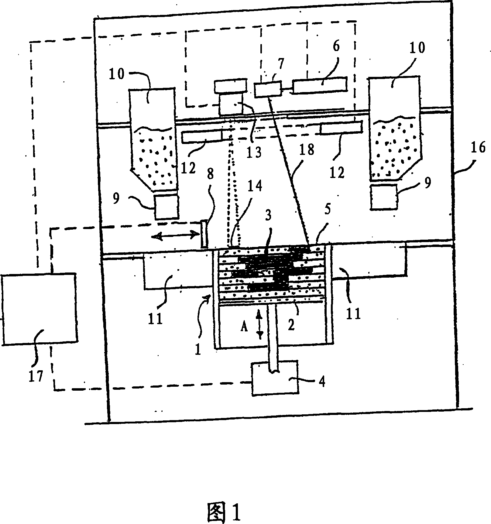
[0018] FIG. 1 shows a laser sintering apparatus as an example of an apparatus for manufacturing a three-dimensional object, in which apparatus and method of the present invention are employed. The laser sintering device has a container 1 opening upwards. A support 2 for supporting an object 3 to be formed is arranged in the container 1 . The support 2 can be moved up and down in the vertical direction 1 within the container 1 by means of a drive device 4 . The upper edge of the container 1 defines a working plane 5 (manufacturing area). Arranged above the working plane 5 is an irradiation device 6 in the form of a laser, which emits a directed laser beam which is deflected onto the working plane 5 by means of a deflection device 7 . Next, an applicator 8 is provided for applying the powder material to be cured to the surface of the carrier 2 or to a recently cured layer. The applicator 8 can be moved back and forth between two end positions above the working plane 5 by mean...
PUM
 Abstract
Description
Claims
Application Information