Eureka AIR delivers breakthrough ideas for toughest innovation challenges, trusted by R&D personnel around the world.

Leveling machine for single beam

A single-piece beam and leveling machine technology, applied in the field of leveling machines, can solve the problems of large center distance of work rolls, affecting the quality of steel plate leveling, large volume, etc., and achieve the effect of improving accuracy

Inactive Publication Date: 2007-12-26
王小建 +1
View PDF0 Cites 0 Cited by
  • Summary
  • Abstract
  • Description
  • Claims
  • Application Information

AI Technical Summary

Problems solved by technology

[0002] In the existing single-piece beam leveling machine, the pressing oil cylinder installed on each single-piece beam is single. Due to the relatively large volume of a single oil cylinder, the center distance between the work rolls is too large, which affects the leveling of the steel plate. Leveling quality, especially leveling accuracy of thin sheets

Method used


Image

  • Leveling machine for single beam
  • Leveling machine for single beam

Examples


Embodiment Construction

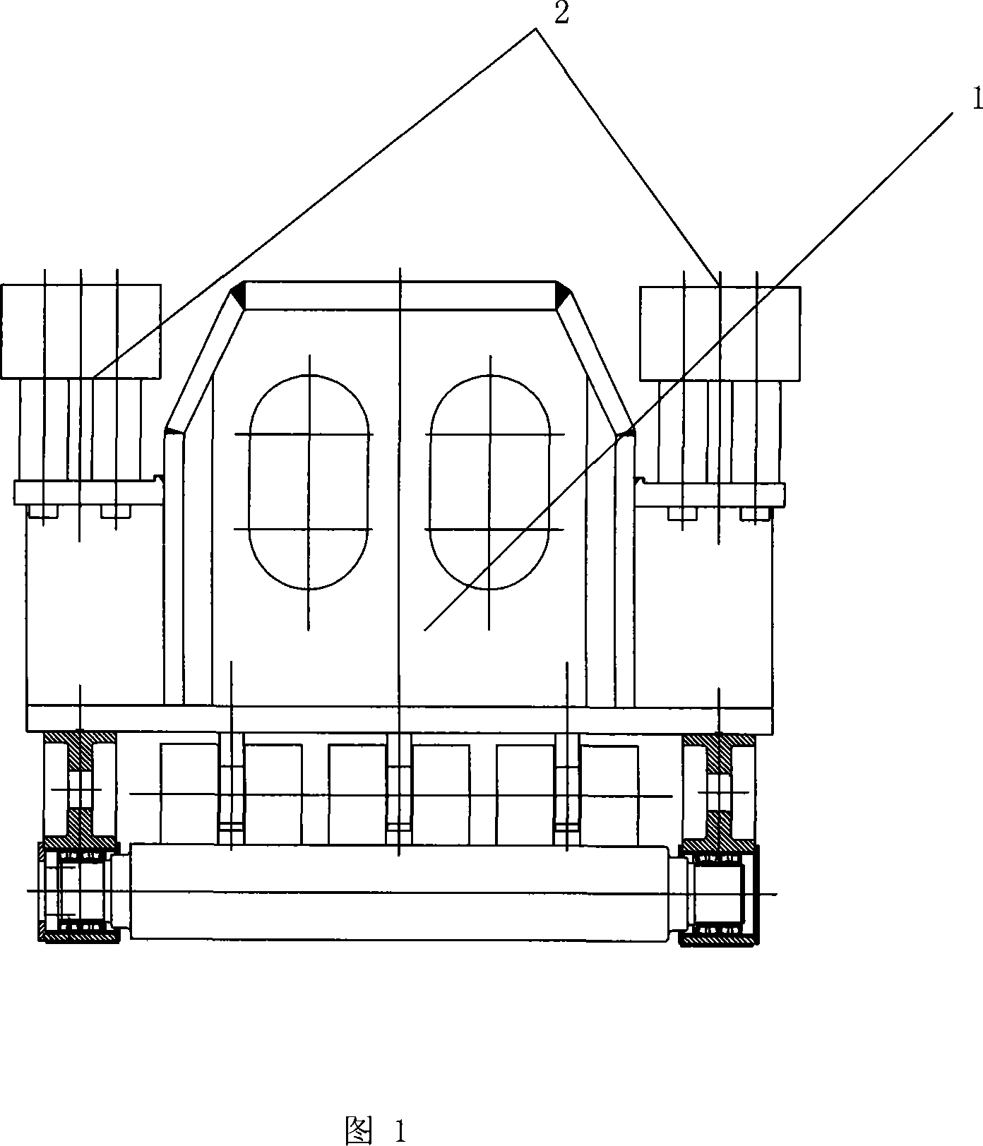
[0010] The present invention will be further described below in conjunction with the accompanying drawings. As shown in Fig. 1 and Fig. 2, the present invention discloses a single-piece beam leveling machine, comprising a single-piece beam 1 and an oil cylinder 2, and the oil cylinder 2 of the upper device at both ends of each single-piece beam 1 can be two one or more.

[0011] The single beam can be one or more of them, and there can be two or more oil cylinders installed on each head.

[0012] The oil cylinder can be a connected cylinder, a plunger cylinder, a sleeve cylinder, or a mixture of a piston cylinder and a plunger cylinder.


PUM


Abstract

The invention discloses a single beam leveler, comprising single beams, and oil cylinders, where the number of oil cylinders set on the two ends of each single beam is two or more. And it can use multiple oil cylinders to bear the pressure on an existing oil cylinder and its bulk is reduced as compared with that of a single oil cylinder, the central distance between working rollers can be regulated to the minimum so as to enlarge its process range, thus largely improving steel plate leveling precision.

Description

technical field [0001] The invention relates to a leveling machine, in particular to a single beam leveling machine. Background technique [0002] In the existing single-piece beam leveling machine, the pressing oil cylinder installed on each single-piece beam is single. Due to the relatively large volume of a single oil cylinder, the center distance between the work rolls is too large, which affects the leveling of the steel plate. Leveling quality, especially the leveling accuracy of thin plates. Contents of the invention [0003] In order to solve the deficiencies of the prior art, the present invention provides a single beam leveler, which uses a plurality of small oil cylinders to press down, so that the center distance between the work rolls can be adjusted to be smaller, and the process range of the leveler is expanded. [0004] In order to achieve the above object, the technical solution of the present invention is a monolithic beam leveling machine, comprising a ...

Claims


Application Information

Patent Timeline
IPC IPC(8): B21D1/00
Inventor 王小建田衍新
Owner 王小建
Why Eureka
Eureka Blog
Learn More