
Manipulation device for wheelchair footrests

一种操作装置、脚底板的技术,应用在运输和包装、车辆的救护方面、病人的椅子或专用运输工具等方向,能够解决使用处理有难度、难以清洗、操作杆误操作等问题,达到安全性优越、易于清洗、简单安装的效果

Inactive Publication Date: 2008-01-02
藤原孝次
View PDF2 Cites 9 Cited by
  • Summary
  • Abstract
  • Description
  • Claims
  • Application Information

AI Technical Summary

Problems solved by technology

[0007] In the wheelchair described in Patent Document 1, there is always an urging device such as a coil spring that urges the open position (standby position) where the sole of the foot is raised upward. Therefore, not only the structure is complicated, but also when the sole of the foot When attached dirt and bacteria adhere to the force applying device, it is difficult to wash off
In addition, there is a danger that the soles of the feet, which are always urged, will suddenly bounce up to the open position (standby position) raised up due to misoperation of the operating lever, which makes it difficult to use and handle.
In addition, in order to adjust the height of the soles of the feet, the operating pull cord as the operating device is quite slack, but if the slack operating draw cord is caught by other objects, it may cause misoperation of the operating lever.
[0008] On the other hand, the sole operating device described in Patent Document 2 was proposed by the inventor of the present application, but the specific technical structure of the operating device for linking the operating rod and the sole of the foot is not fully disclosed.

Method used


Image

  • Manipulation device for wheelchair footrests
  • Manipulation device for wheelchair footrests
  • Manipulation device for wheelchair footrests

Examples


Embodiment Construction

[0068] Hereinafter, preferred embodiments of the present invention will be described with reference to the accompanying drawings.

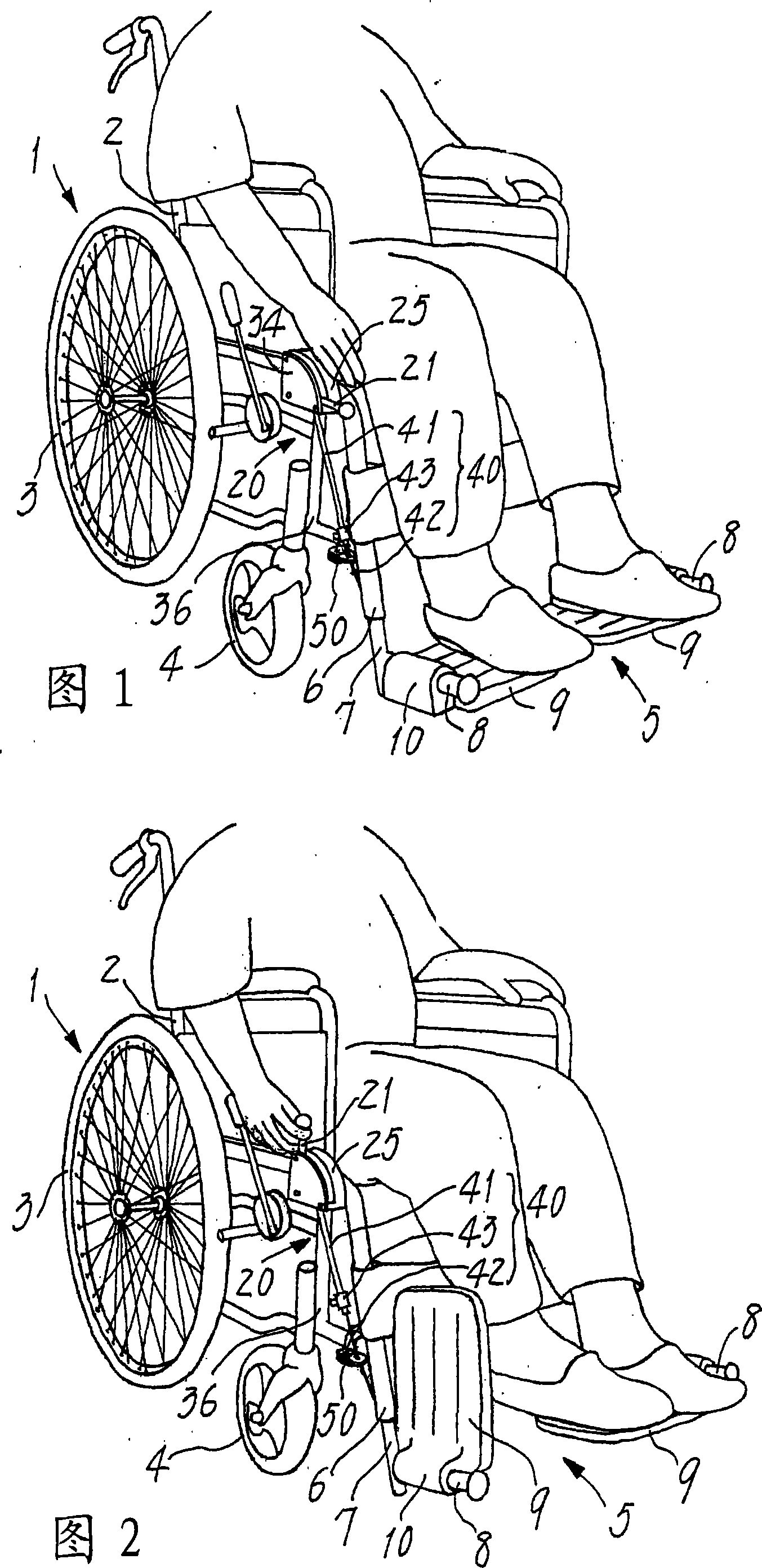
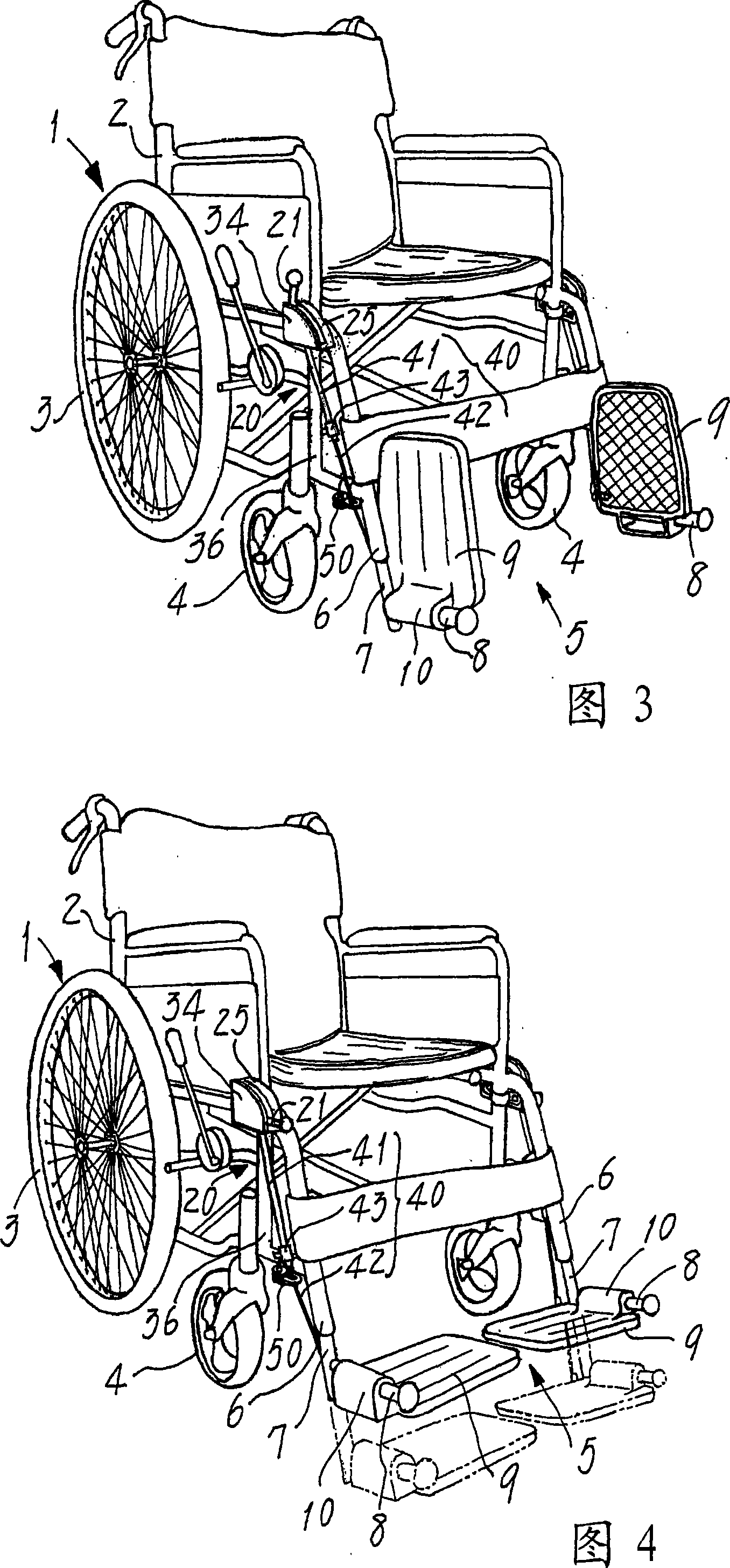
[0069] 1 and 2 show a use state of the wheelchair 1 to which the footrest operating device of the present invention is attached. Since the wheelchair 1 itself is the same as a commercially available existing wheelchair, in order to describe its general structure, basically, a large-diameter rear wheel 3 and a small-diameter front wheel 4 are attached to the main body frame 2 formed of a metal tube. The structure is formed, and a footrest 5 is provided on the front side of the main body frame 2 .

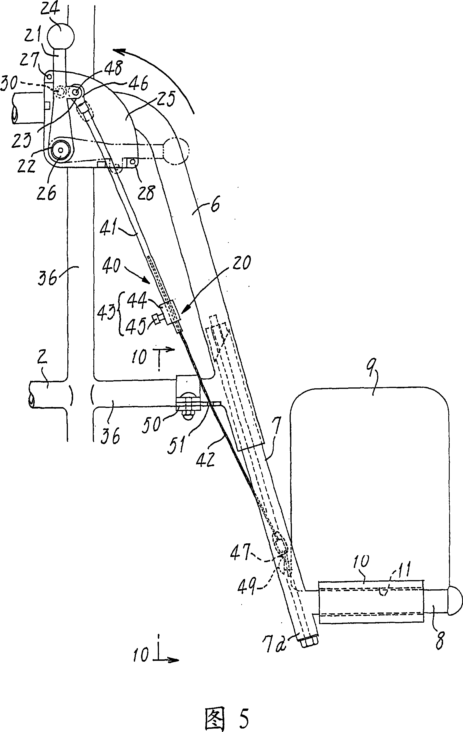
[0070] The footboard 5 is constituted as follows: support tubes 6 and 6 are formed on both sides of the front part of the main body frame 2 , lift tubes 7 and 7 with adjustable lift lengths are installed on the two support tubes 6 and 6 , and the two lift tubes A pair of mounting shafts 8 and 8 extending forward are protruded from the lower ends of 7 an...


PUM


Abstract

A manipulation device is for wheelchair footrests that have a pair of shafts ( 8 ) extending forwards from opposite forward sides of the main frame ( 2 ) and a pair of foot plates ( 9 ) pivoted at lateral portions to the shafts. This device has manual levers ( 21 ) at the forward sides and actuating means ( 40 ) that connects the levers ( 21 ) to foot plates ( 9 ) and consists of a resilient tube ( 41 ), a metal wire ( 42 ) and a setting retainer ( 43 ) for securing the tube to the wire. The tube ( 41 ) can elongate in response to an extraordinary tension exceeding a normal stress imparted to said tube, and the wire ( 42 ) loosely inserted in the tube ( 41 ) can alter an exposed length. An end of each wire ( 42 ) is connected to the foot plate ( 9 ) at its rear portion located near the shaft ( 8 ) pivoting the foot plate. An end of each tube ( 41 ) is connected to the manual lever ( 21 ) operating to pull up the tube ( 41 ) with the wire ( 42 ) such that the foot plate ( 9 ) rotates and rises to the upright idle position.

Description

technical field [0001] The present invention relates to a footrest operating device of a wheelchair, which is provided with a footrest having a footrest on which a wheelchair user can place their feet. Background technique [0002] A footrest of such a conventional wheelchair has a pair of footplates, and the pair of footplates is pivotally supported by a pair of mounting shafts extending forward from both sides of the front part of the main body frame, and the footplates are configured as Can be rotated between a laterally approaching use position (closed position) and an upright stand-by position (open position), and to prevent accidental pivoting of the soleplate from the upright open position to the laterally closed position , On the pivot support part between the foot bottom plate and the installation shaft, there is a locking device using the forced friction force generated by springs, screws, etc. [0003] In addition, when the wheelchair user gets on and off the whe...

Claims


Application Information

Patent Timeline
Patent Type & Authority Applications(China)
IPC IPC(8): A61G5/10
CPCA61G5/12A61G2005/128A61G2005/1054A61G5/1054A61G5/128A61G5/10
Inventor 藤原孝次藤原孝明
Owner 藤原孝次
Learn More