Robot for industry

A technology for industrial robots and detection sensors, which is applied in manipulators, manufacturing tools, program-controlled manipulators, etc., can solve problems such as indoor heat generation, drive source heat generation, and rising cooling costs, and achieve efficient cooling costs, improved action safety, and cooling The effect of cost containment

Active Publication Date: 2008-01-02
NIDEC SANKYO CORP
View PDF2 Cites 18 Cited by
  • Summary
  • Abstract
  • Description
  • Claims
  • Application Information

AI Technical Summary

Problems solved by technology

This recirculation of large volumes of cooling air will result in increased cooling costs
[0008] In addition, when a process involving heat generation such as CVD (Chemical Vapor Deposition) process used

Method used


Image

  • Robot for industry
  • Robot for industry
  • Robot for industry

Examples


Example Embodiment

[0060] Hereinafter, the best mode for carrying out the present invention will be described with reference to the drawings. The industrial robot of the present invention is not limited to the following description and drawings as long as it has its technical features. In the following description, a commonly used motor (arm drive motor) is used as an example of a drive source. Of course, the drive source used in the present invention is not limited to a motor. In addition, in accordance with the description using a motor as an example, the storage chamber that stores the drive source is referred to as a "motor storage chamber". Similarly, the part that houses the drive source in the housing chamber is referred to as the "motor housing part".

[0061] [First Embodiment]
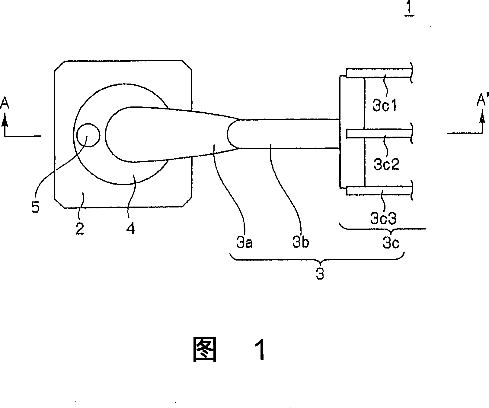
[0062] Fig. 1 shows a schematic plan view of an industrial robot according to a first embodiment of the present invention. The industrial robot 1 shown in FIG. 1 is a type in which the arm rotates, and includes: a ...


PUM


Abstract

The invention relates to an industrial robot operated in doors under a decompressed atmosphere, which can reliably and effectively cool the motor for driving the arm of the said robot. The industrial robot (1) comprises arm part (3) and storage room (4) where a driving source (6) for operating said arm part was stored, wherein the said arm part and said storage room are installed in a chamber under a decompressed atmosphere. The robot also provides a local hypothermia mechanism which cools said driving source (6) in said storage room. In addition the local cooling is perform by winding the aluminium pipe in which compressed air can circulate around the periphery of the motor for arm driving.

Description

technical field [0001] The present invention relates to an industrial robot, and more particularly to an industrial robot used in a decompressed atmosphere such as liquid crystal manufacturing equipment and semiconductor manufacturing equipment. Background technique [0002] In an industrial robot installed in a room under a reduced pressure atmosphere (more specifically, under a vacuum), it is important to remove heat generated by a motor or the like mounted inside the industrial robot. [0003] As a technique for removing heat generated in an industrial robot installed in a chamber under a decompressed atmosphere (hereinafter also referred to as a "vacuum chamber" as appropriate), Patent Document 1 discloses that the cooling gas can be A cooling mechanism that circulates all parts inside an industrial robot that houses many heat-generating parts such as motors. The cooling mechanism shown in FIG. 1 of this document is described with the symbols in the same figure. The coo...

Claims


Application Information

Patent Timeline
IPC IPC(8): B25J3/00B25J13/00B25J19/00
CPCB25J9/02B25J13/087B25J19/0054B25J19/02B25J19/06
Inventor 矢泽隆之柴真砂
Owner NIDEC SANKYO CORP
Why Eureka
Try Eureka