
Platform type disk sawing machine

A disc sawing machine and desktop technology, which is applied in the field of desktop circular sawing machines, can solve the problems of deformation and damage of the safety cover 65, and achieve the effect of preventing the damage of the safety cover

Inactive Publication Date: 2010-10-20
MAKITA CORP
View PDF7 Cites 0 Cited by
  • Summary
  • Abstract
  • Description
  • Claims
  • Application Information

AI Technical Summary

Problems solved by technology

Thus, there arises a problem that the safety cover 65 is deformed or damaged due to the pressing force of the stopper member 61 (the spring-loaded force of the top dead center locking mechanism) pressed against the side.

Method used


Image

  • Platform type disk sawing machine
  • Platform type disk sawing machine
  • Platform type disk sawing machine

Examples


Embodiment Construction

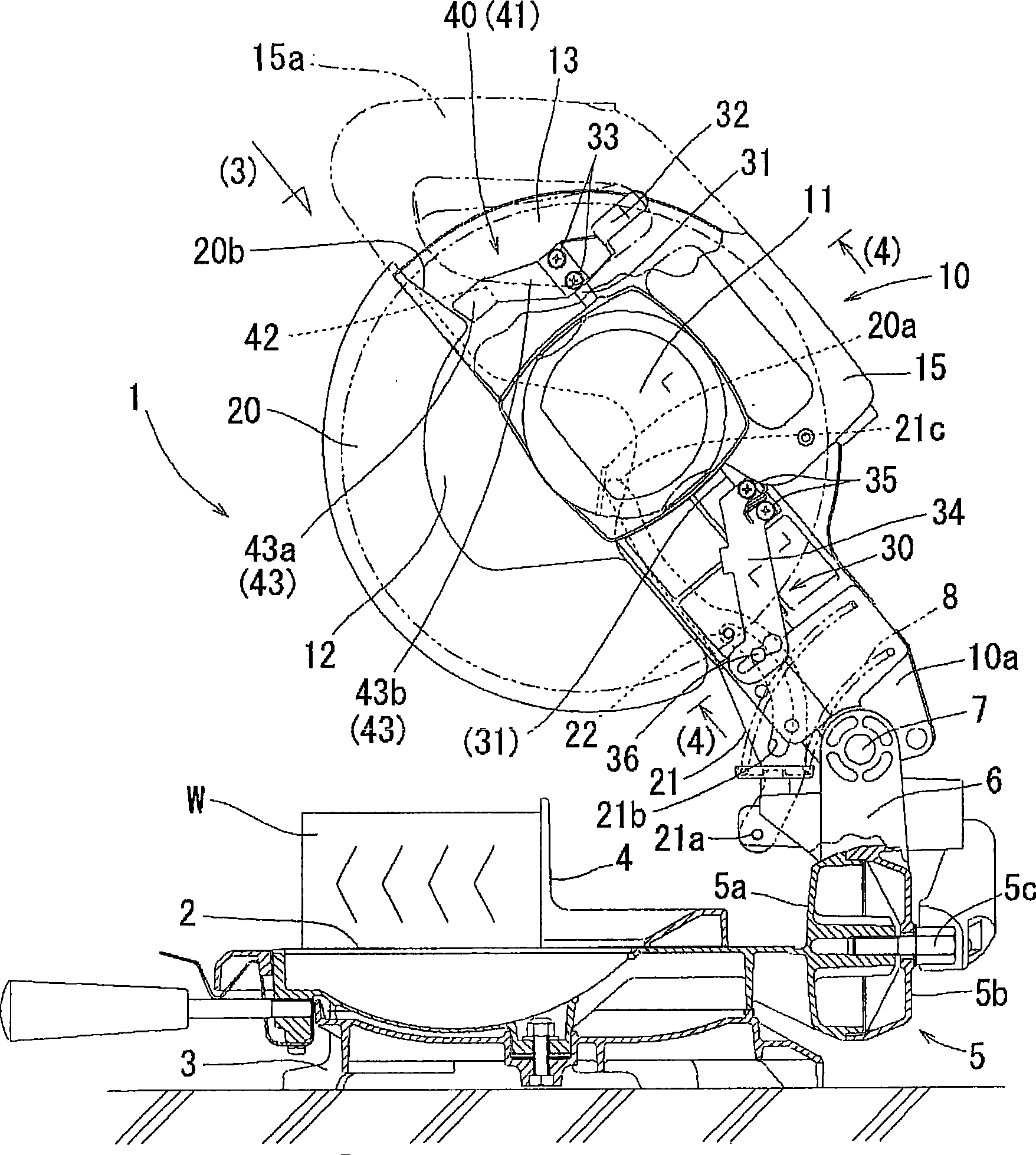
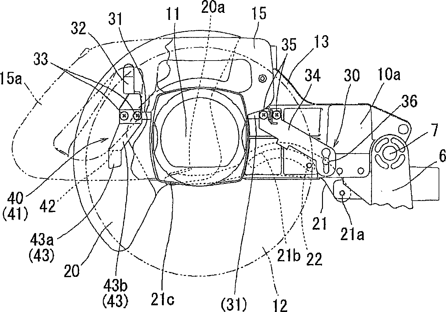
[0036] Below, based on Figure 1 to Figure 10 Embodiments of the present invention will be described. figure 1 The desktop circular saw machine 1 of this embodiment is shown. This table-type circular sawing machine 1 has: a table 2 on which a cutting member W is fixed; The table 2 is supported on the upper surface of the base 3 in a horizontally rotatable manner. A positioning fence 4 for positioning the cutting material W is arranged on the upper surface side of the table 2 . The positioning guardrail 4 is installed on the side of the base 3 and has a slight gap with the upper surface of the workbench 2 , the gap is so small as long as it does not interfere with the upper surface of the workbench 2 .

[0037] At the rear of Workbench 2 (at the figure 1 A support arm 6 is provided on the right end portion in the center) with a left and right tilting action support portion 5 interposed therebetween. A tilting base 10a of the cutter main body 10 is supported on the front ...


PUM


Abstract

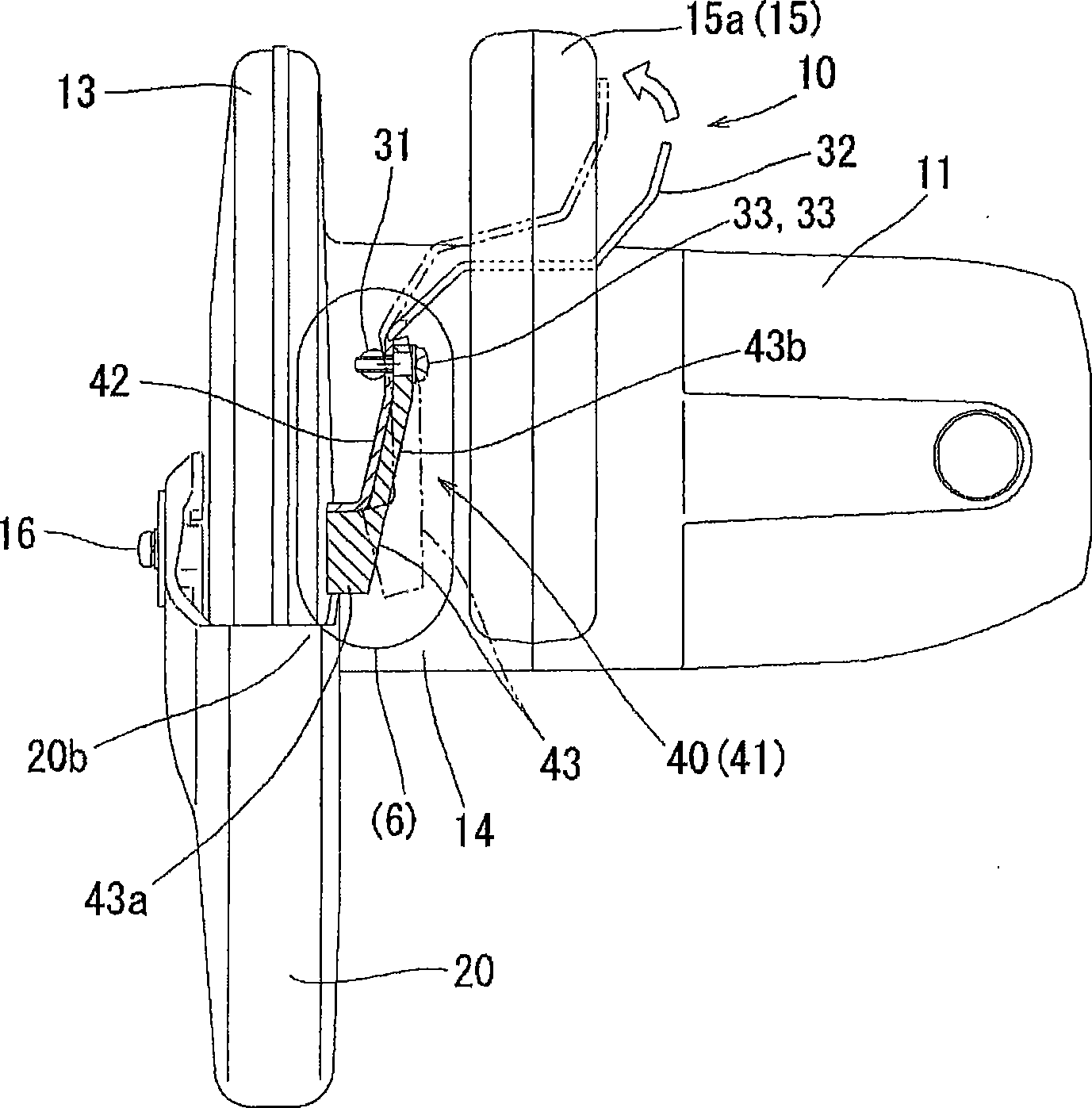
The invention relates to a desk circular saw machine. The begone stopper member is pressed on the side of the safety cup to form moving resistance, therefore the safety cup maybe not rotate smoothly, wherein the stopper member is used to locking the safety up which rotates relative to cutter shield to switch the cutter at the dead point on the main body of cutting-off machine to make it not open.In the said invention, even the stopper member is bunted with the side, the safety cup will rotate smoothly. The stopper member (41) is separated into stopper supporter (42) and stopper main body (43), and a second energizing unit (43b) is mounted betweent the two parts, to make the energized force on the restrict part (43a) of the stopper main body (43) less than the first energized force of the dead point locking mechanism.

Description

technical field [0001] The present invention relates to a table-type circular sawing machine for cutting a cutting piece fixed on a workbench by moving the main body of the cutting machine up and down. Background technique [0002] Such a table-type circular sawing machine has a table for fixing a cutting material, and a cutting machine main body supported on the table so as to be movable up and down, and the cutting machine main body has a circular saw blade rotated by a motor. [0003] Approximately half of the upper side of the saw blade is covered by the knife guard, and approximately half of the lower side of the saw blade protruding downward from the knife guard is covered by the safety cover. The safety cover is opened and closed in conjunction with the vertical movement of the cutting machine main body. That is, when the main body of the cutting machine moves downward, the safety cover is slowly opened to expose the saw blade, so that the exposed part of the saw bla...

Claims


Application Information

Patent Timeline
Patent Type & Authority Patents(China)
IPC IPC(8): B28D1/04
Inventor 青山修司
Owner MAKITA CORP
Learn More