Saw blade with lateral buckles

A saw blade and circular technology, applied in the direction of manufacturing tools, metal sawing equipment, stone processing tools, etc., can solve the problems of imprecise cutting, high material cost, etc., and achieve the effect of cheap manufacturing, improved precision, and good sturdiness

Inactive Publication Date: 2008-01-02
HILTI AG
View PDF1 Cites 2 Cited by
  • Summary
  • Abstract
  • Description
  • Claims
  • Application Information

AI Technical Summary

Problems solved by technology

During operation, the region prevents excessive heating caused by friction and the resulting deformation of the saw blade, which leads to imprecise cutting
[0004] A disadvantage with known saw blades is the relatively high material costs

Method used


Image

  • Saw blade with lateral buckles
  • Saw blade with lateral buckles
  • Saw blade with lateral buckles

Examples


Embodiment Construction

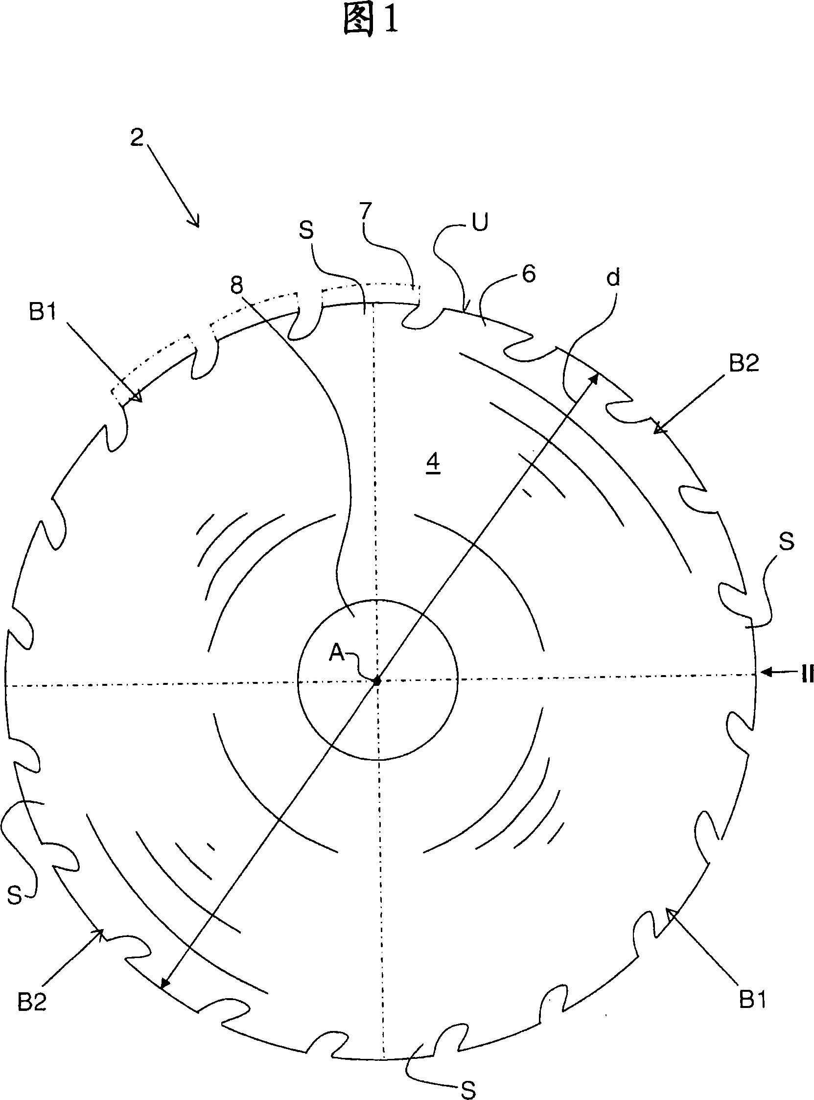
[0016] FIG. 1 shows a saw blade 2 for processing mineral material in the form of a wall saw blade with a diameter d of up to 800 mm. The saw blade has a main blade 4 , for example made of steel, on which processing means 6 in the form of cutting teeth are held. The cutting teeth can hereby be formed in one piece with the core piece 4 or at least partially consist of a special material which is applied to the core piece 4 . Instead of or in combination with the cutting teeth, diamond bodies can also be arranged on the circumference U of the saw blade 2 . In this case, diamond segments 7 can be arranged on a circumference U, for example, as indicated by dashed lines in FIG. 1 .

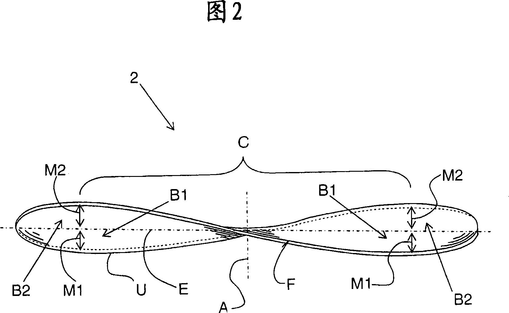
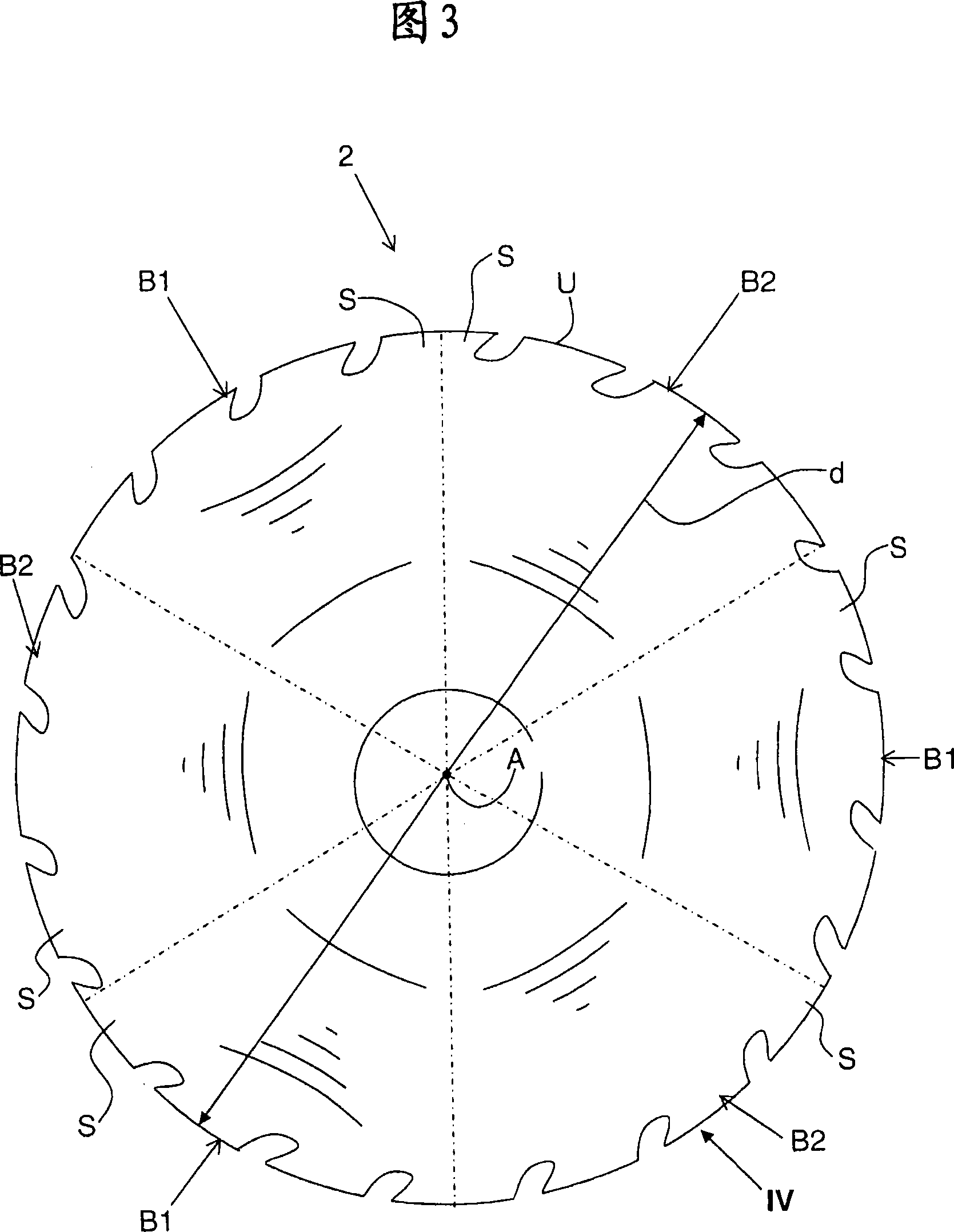
[0017] For fastening on a tool holder of a power tool not described, the power tool drives a saw blade 2 , which has a central bore 8 , in rotation about an axis A in the circumferential direction. In addition, the saw blade 2 is divided into four sectors S of equal size, each sector alternately havin...


PUM

PropertyMeasurementUnit
diameteraaaaaaaaaa
diameteraaaaaaaaaa

Abstract

A circular saw blade ( 2 ) includes at least two sectors (S) following each other in a circumferential direction and each having an axial run-out region (B 1 , B 2 ), with the following each other axial run-out regions (B 1 , B 2 ) directed to opposite sides of the blade saw ( 2 ) relative to a saw middle plane (E), and a working element ( 6 ), preferably a diamond body, provided on a circumference (U) of the saw blade.

Description

technical field [0001] The invention relates to a circular saw blade, in particular for working natural or artificial stone, for example in the form of concrete walls. The saw blade has processing means such as cutting means or grinding means or combinations thereof on its circumference. In this case, the cutting or grinding device can be formed, for example, by a diamond body, cutting teeth or a combination of both. Background technique [0002] Such a saw blade is fastened via a central hole to a tool holder of the corresponding machine tool and is rotated by the machine tool during operation. [0003] A circular saw blade is known from EP 1 270 126 A1 with a support disk, on the circumference of which cutting elements are arranged. In addition, particularly wear-resistant regions are provided on the sides of the support disk. During operation, the region prevents excessive heating of the saw blade by friction and the resulting deformation of the saw blade, which leads ...

Claims


Application Information

Patent Timeline
Patent Type & Authority Applications(China)
IPC IPC(8): B28D1/04
CPCY10T83/9408B28D1/121B23D61/025Y10T83/9346
Inventor C·韦伯C·科万达
Owner HILTI AG
Why Eureka
Try Eureka