Printing apparatus

A technology of printing equipment and platen rollers, applied in printing devices, printing, typewriters, etc., can solve the problems of damage or wear of each component, increase of paper conveying resistance, and troublesome conveying.

Active Publication Date: 2008-01-02
TOSHIBA TEC KK +1
View PDF2 Cites 25 Cited by
  • Summary
  • Abstract
  • Description
  • Claims
  • Application Information

AI Technical Summary

Problems solved by technology

[0013] Therefore, when the paper is reversely fed so that the printing start positions are aligned with each other, the reverse supply amount of the paper by the platen roller of the first printing unit becomes larger than that of the platen roller of the second printing unit, causin

Method used


Image

  • Printing apparatus
  • Printing apparatus
  • Printing apparatus

Examples


no. 1 example

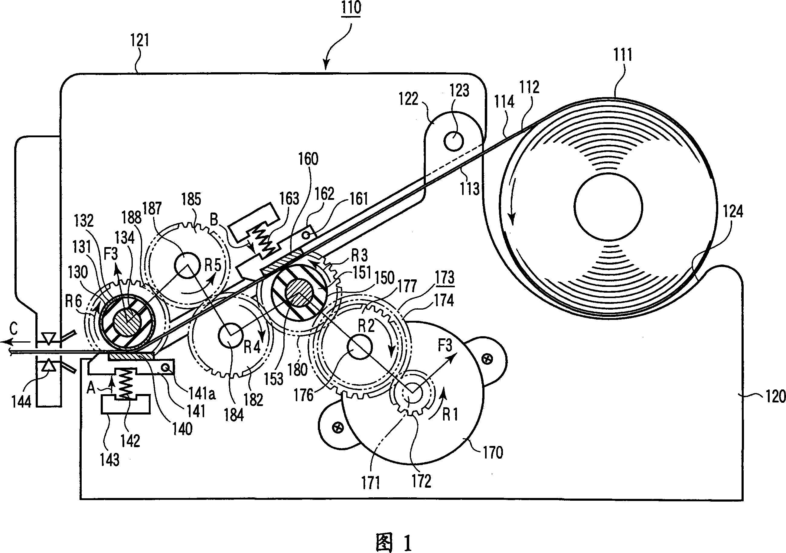
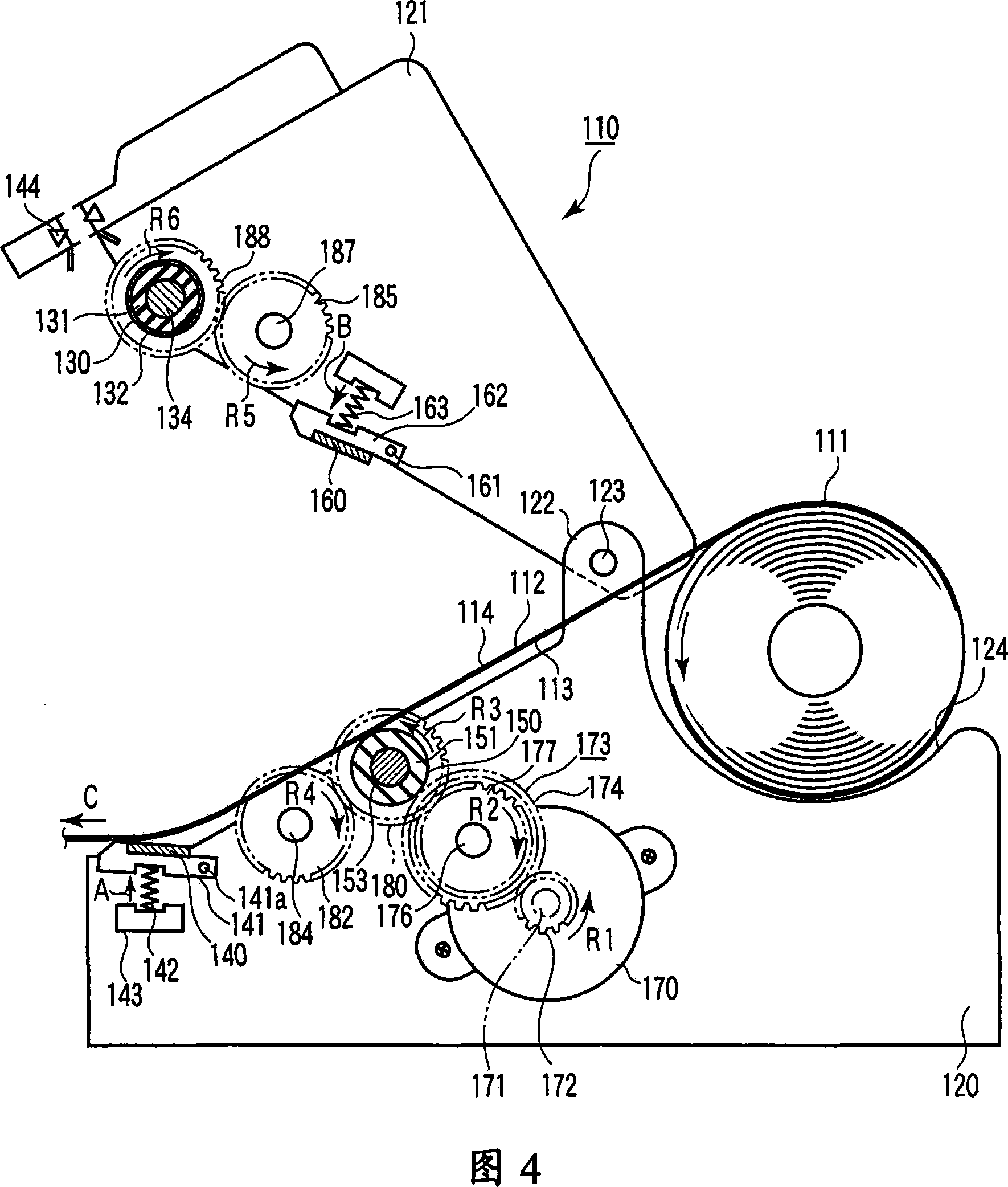
[0054] FIG. 1 schematically shows the interior of a thermal printer 110 according to a first embodiment of the present invention. The thermal printer 110 can print on both surfaces of the thermal recording paper 111 . For example, thermal printer 110 may be used in a cash register at a store.

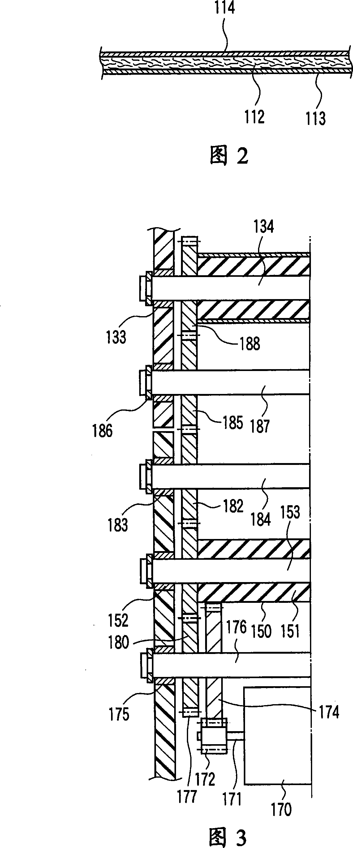
[0055] As shown in FIG. 2 , the thermosensitive recording paper 111 includes a base paper 112 and thermosensitive layers 113 and 114 formed on both surfaces of the base paper 112 . The first thermosensitive layer 113 is formed on one side (eg, the surface) of the base paper 112 , and the second thermosensitive layer 114 is formed on the other side (eg, the back side) of the base paper 112 . Each heat-sensitive layer 113 and 114 is made of a material that develops a desired color, such as black and red, when heated to a predetermined temperature or higher. As shown in FIG. 1 , the thermosensitive recording paper 111 is wound in a roll shape such that the first thermosensitive layer 113...

no. 2 example

[0087] A thermal printer 190 according to a second embodiment of the present invention will be described below. The second embodiment differs from the first embodiment only in first and second platen rollers 130 and 150 and first and second biasing devices 191 and 192 . Therefore, the same components are denoted by the same reference numerals, and descriptions thereof are omitted.

[0088] In the second embodiment, the first platen roller 130a and the second platen roller 150a are composed of roller bodies 131a and 151a made of NBR, respectively. The first platen roller 130a is slightly larger in diameter than the second platen roller 150a.

[0089] The first biasing device 191 is smaller in spring constant than the second biasing device 192 . For example, the spring wire diameter of the first biasing device 191 is smaller than the spring wire diameter of the second biasing device 192 . Therefore, the force with which the first thermal head 140 presses against the first pla...

no. 3 example

[0096] FIG. 6 schematically shows the interior of the thermal printer 210 . The thermal printer 210 can print on both surfaces of the thermal recording paper 211 . For example, thermal printer 210 may be used in a cash register at a store.

[0097] As shown in FIG. 7 , the heat-sensitive recording paper 211 includes a base paper 212 and heat-sensitive layers 213 and 214 formed on both surfaces of the base paper 212 . The first thermosensitive layer 213 is formed on one side (eg, the surface) of the base paper 212 , and the second thermosensitive layer 214 is formed on the other side (eg, the back side) of the base paper 212 . Each heat-sensitive layer 213 and 214 is made of a material that develops a desired color, such as black and red, when heated to a predetermined temperature or higher. As shown in FIG. 6, the heat-sensitive recording paper 211 is wound in a roll shape such that the first heat-sensitive layer 213 faces inside.

[0098] The thermal printer 210 includes a...


PUM


Abstract

A thermal printer (110) includes a first thermal head (140), a first platen roller (130), first biasing means (142), a second thermal head (160), a second platen roller (150), and second biasing means (163). The first thermal head (140), the first platen roller (130), the first biasing means (142) are in contact with a heat-sensitive layer of thermal recording paper (113). The second thermal head(160), the second platen roller (150), and the second biasing means (163) are in contact with a heat-sensitive layer of the thermal recording paper (114). The second thermal head (160) is arranged onthe upstream side of the first thermal head (140) in a paper feed direction. A paper feed speed of the first platen roller (130) to the thermal recording paper (111) is larger than a paper feed speedof the second platen roller (150). The first platen roller (130) is in contact with the thermal recording paper (111) while being more slippery compared with the second platen roller (150).

Description

[0001] Related Application Cross Reference [0002] This application is based on and claims the benefit of the following prior Japanese patent applications: No. 2006-178941 filed June 29, 2006, No. 2006-178942 filed June 29, 2006, June 29, 2006 No. 2006-178943 filed on June 29, 2006, No. 2006-178950 filed on June 29, 2006, No. 2006-178952 filed on June 29, 2006, Nos. 2006-178954, filed June 29, 2006, and 2006-178955, filed June 29, 2006, the entire contents of which are hereby incorporated by reference. technical field [0003] The present invention relates to a printing apparatus, and more particularly, to a technique in which paper can be conveyed smoothly and a technique in which a long service life and high reliability are obtained. Background technique [0004] Currently, thermal printers are used in restaurants and stores to print receipts with registration numbers. Receipts are usually printed on one side, and a large amount of receipt paper will be used if a large ...

Claims


Application Information

Patent Timeline
IPC IPC(8): B41J3/54B41J11/04B41J15/04B41J2/32
Inventor 关野利治江冈健二二桥清刚日吉武司真田强铃木彰
Owner TOSHIBA TEC KK
Why Eureka
Try Eureka